INSTALL TORQUE CONVERTER CLUTCH ASSEMBLY (for Automatic Transaxle)
INSTALL CLUTCH RELEASE CYLINDER ASSEMBLY (for Manual Transaxle)
INSTALL TRANSAXLE CONTROL CABLE ASSEMBLY (for Manual Transaxle)
INSTALL TRANSAXLE CONTROL CABLE ASSEMBLY (for Automatic Transaxle)
Engine Assembly -- Installation |
| 1. INSTALL FLYWHEEL SUB-ASSEMBLY (for Manual Transaxle) |
Clean the 8 bolts and 8 bolt holes.
Apply adhesive to 2 or 3 threads of the 8 bolts.
- Adhesive:
- Part No. 08833-00070, THREE BOND or equivalent
Using SST, hold the crankshaft.
- Специальный инструмент (SST):
- 09213-54015(91651-60855)
09330-00021
 |
Using several steps, uniformly install and tighten the 8 bolts in the sequence shown in the illustration.
- Момент затяжки:
- 130 Н*м{1,326 кгс*см, 96 фунт-сила-футов}
 |
| 2. INSTALL CLUTCH DISC ASSEMBLY (for Manual Transaxle) |
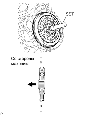 |
Вставьте SST в диск, а затем – в маховик.
- Специальный инструмент (SST):
- 09301-00210
- ПРИМЕЧАНИЕ:
- Следите за тем, чтобы ведомый диск сцепления был вставлен правильной стороной.
| 3. INSTALL CLUTCH COVER ASSEMBLY (for Manual Transaxle) |
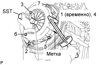 |
Совместите сборочные метки кожуха сцепления и маховика.
Равномерно затяните 6 болтов в последовательности, показанной на рисунке, начиная с болта, который расположен сверху около штифта.
- Момент затяжки:
- 19 Н*м{195 кгс*см, 14 фунт-сила-футов}
- УКАЗАНИЕ:
- Заворачивайте болты равномерно, по одному, в последовательности, показанной на рисунке.
- Проверьте, чтобы диск располагался по центру, а затем, осторожно перемещая SST вверх-вниз и вправо-влево, затяните болты.
- Специальный инструмент (SST):
- 09301-00210
| 4. INSTALL MANUAL TRANSAXLE ASSEMBLY (for Manual Transaxle) |
Install the manual transaxle for E352 (2WD) (see page RAV4_ACA30 RM000001YVM000X_01_0002.html).
Install the manual transaxle for E359F (4WD) (see page RAV4_ACA30 RM000001YVM001X_01_0002.html).
| 5. INSTALL STIFFENER PLATE RH (for Manual Transaxle) |
 |
Install the stiffener plate with the 4 bolts.
- Момент затяжки:
- 46 Н*м{469 кгс*см, 34 фунт-сила-футов}
| 6. INSTALL STIFFENER PLATE LH (for Manual Transaxle) |
 |
Install the stiffener plate with the 4 bolts.
- Момент затяжки:
- 46 Н*м{469 кгс*см, 34 фунт-сила-футов}
| 7. INSTALL FLYWHEEL HOUSING UNDER COVER (for Manual Transaxle) |
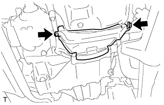 |
Install the insulator with the 2 bolts.
- Момент затяжки:
- 9.0 Н*м{92 кгс*см, 80 фунт-сила-дюймов}
| 8. INSTALL DRIVE PLATE SUB-ASSEMBLY (for Automatic Transaxle) |
Clean the 8 bolts and 8 bolt holes.
Apply adhesive to 2 or 3 threads of the 8 bolts.
- Adhesive:
- Part No. 08833-00070, THREE BOND or equivalent
Using SST, hold the crankshaft.
- Специальный инструмент (SST):
- 09213-54015(91651-60855)
09330-00021
|
Install the front spacer.
- УКАЗАНИЕ:
- Align the pin of the front spacer with the pin hole of the crankshaft.
 |
Install the drive plate and rear spacer onto the crankshaft.
 |
Using several steps, uniformly install and tighten the 8 bolts in the sequence shown in the illustration.
- Момент затяжки:
- 98 Н*м{1,000 кгс*см, 72 фунт-сила-футов}
 |
| 9. INSTALL TORQUE CONVERTER CLUTCH ASSEMBLY (for Automatic Transaxle) |
Install the torque converter clutch for U241E (2WD) (see page RAV4_ACA30 RM000001SUK001X_01_0002.html).
Install the torque converter clutch for U140F (4WD) (see page RAV4_ACA30 RM000001SUK000X_01_0002.html).
| 10. INSTALL AUTOMATIC TRANSAXLE ASSEMBLY |
Install the automatic transaxle for U241E (2WD) (see page RAV4_ACA30 RM000001SUK001X.html).
Install the automatic transaxle for U140F (4WD) (see page RAV4_ACA30 RM000001SUK000X_01_0003.html).
| 11. INSTALL STARTER ASSEMBLY |
Install the starter for 1.6 kW Type (see page RAV4_ACA30 RM000000YQ1007X_01_0001.html).
Install the starter for 1.7 kW Type (see page RAV4_ACA30 RM000000YQ1008X_01_0001.html).
| 12. INSTALL TRANSFER ASSEMBLY (for 4WD) |
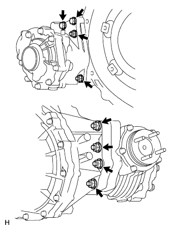 |
Установите раздаточную коробку на трансмиссию и закрепите ее 6 гайками и 2 болтами.
- Момент затяжки:
- 69 Н*м{700 кгс*см, 51 фунт-сила-футов}
| 13. INSTALL DRIVE SHAFT BEARING BRACKET (for 2WD) |
Install the bracket with the 3 bolts.
- Момент затяжки:
- 64 Н*м{653 кгс*см, 47 фунт-сила-футов}
 |
| 14. INSTALL DRIVE SHAFT BEARING BRACKET (for 4WD) |
Install the bracket with the 3 bolts.
- Момент затяжки:
- 64 Н*м{653 кгс*см, 47 фунт-сила-футов}
 |
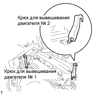
| 15. INSTALL ENGINE HANGER |
Install the No. 1 and No. 2 engine hangers.
- Момент затяжки:
- 38 Н*м{387 кгс*см, 28 фунт-сила-футов}
- Part No. :
Item Part No. No. 1 engine hanger 12281-28010 No. 2engine hanger 12282-28010 Bolt 91512-61020
 |
Attach the sling device and the engine with the chain block.
| 16. INSTALL ENGINE ASSEMBLY WITH TRANSAXLE |
Set the engine assembly with transaxle on the engine lifter.
Slowly lower the engine assembly into the engine compartment.
- ПРИМЕЧАНИЕ:
- Make sure the engine is clear of all wiring, hoses and cables.
 |
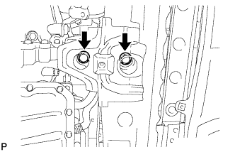
| 17. INSTALL ENGINE MOUNTING INSULATOR LH |
Install the engine mounting insulator LH with the 4 bolts.
- Момент затяжки:
- 95 Н*м{969 кгс*см, 70 фунт-сила-футов}
 |
Install the engine mounting insulator LH with the through bolt and nut.
- УКАЗАНИЕ:
- Install the through bolt by tightening the nut.
- Момент затяжки:
- 56 Н*м{571 кгс*см, 41 фунт-сила-футов}
 |
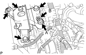
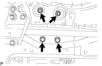
| 18. INSTALL ENGINE MOUNTING INSULATOR RH |
Install the engine mounting insulator RH with the 2 bolts and 2 nuts.
- Момент затяжки:
- 95 Н*м{969 кгс*см, 70 фунт-сила-футов} for bolt
- 95 Н*м{969 кгс*см, 70 фунт-сила-футов} for nut A
- 52 Н*м{530 кгс*см, 38 фунт-сила-футов} for nut B
 |
| 19. REMOVE ENGINE HANGER |
Remove the No. 1 and No. 2 engine hangers.
 |
| 20. INSTALL ENGINE MOUNTING INSULATOR RR |
Install the engine mounting insulator RR with the 2 nuts and 2 bolts.
- Момент затяжки:
- 95 Н*м{969 кгс*см, 70 фунт-сила-футов}
 |
Install the through bolt which is used to secure the rear engine mounting insulator, into the rear engine mounting bracket RR.
- Момент затяжки:
- 95 Н*м{969 кгс*см, 70 фунт-сила-футов}
 |
| 21. INSTALL ENGINE MOUNTING INSULATOR FR |
Install the engine mounting insulator FR with the 2 bolts.
- Момент затяжки:
- 95 Н*м{969 кгс*см, 70 фунт-сила-футов}
 |
Install the through bolt and nut.
- Момент затяжки:
- 145 Н*м{1,479 кгс*см, 107 фунт-сила-футов}
- УКАЗАНИЕ:
- Install the through bolt by tightening the nut.
- УКАЗАНИЕ:
- Install the bolt which is used to secure the front engine mounting bracket FR.
 |
| 22. INSTALL PROPELLER SHAFT ASSEMBLY (for 4WD) |
Install the propeller shaft (see page RAV4_ACA30 RM00000226E000X.html).
| 23. INSTALL FRONT DRIVE SHAFT ASSEMBLY |
Install the front drive shaft (2WD) (see page RAV4_ACA30 RM00000226J000X.html).
Install the front drive shaft (4WD) (see page RAV4_ACA30 RM00000226O000X.html).
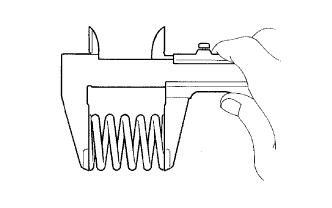
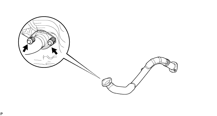
| 24. INSTALL FRONT EXHAUST PIPE ASSEMBLY |
Using a vernier caliper, measure the free length of the compression spring.
- Minimum length:
- 41.5 mm (1.634 in.)
 |
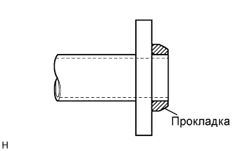
Install a new gasket by hand so that its surface is flush with the exhaust manifold.
- ПРИМЕЧАНИЕ:
- Make sure the gasket is facing the correct direction.
- Do not reuse the removed gasket.
- Do not push in the gasket while installing the front exhaust pipe.
 |
Install the front exhaust pipe with the 2 compression springs and 2 bolts.
- Момент затяжки:
- 43 Н*м{438 кгс*см, 32 фунт-сила-футов}
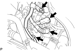
| 25. CONNECT ENGINE WIRE |
Install the ground cable with the bolt located near the starter.
- Момент затяжки:
- 13 Н*м{133 кгс*см, 10 фунт-сила-футов}
 |
Connect the ground cable clamp located near the starter.
Connect the engine wire to the battery positive (+) terminal with the nut.
- Момент затяжки:
- 13 Н*м{133 кгс*см, 10 фунт-сила-футов}
 |
Connect the ground cable connector.
 |
Connect the 2 engine wire connectors and install the nut.
 |
Install the engine room relay block cover.
Attach the clamp of the engine wire cover.
 |
Install the engine wire cable with the bolt.
| 26. INSTALL ECM |
Install the ECM (see page RAV4_ACA30 RM0000017UM001X.html).
| 27. INSTALL COOLER COMPRESSOR ASSEMBLY |
Без шпильки:
Установите компрессор системы кондиционирования и закрепите его 4 болтами.- Момент затяжки:
- 24.5 Н*м{250 кгс*см, 18 фунт-сила-футов}
- ПРИМЕЧАНИЕ:
- При установке компрессора системы кондиционирования затягивайте болты в последовательности, показанной на рисунке.
 |
При наличии шпильки:
Установите компрессор системы кондиционирования и закрепите его 3 болтами и гайкой.- Момент затяжки:
- 24,5 Н*м{250 кгс*см, 18 фунт-сила-футов}
- ПРИМЕЧАНИЕ:
- При установке компрессора системы кондиционирования затягивайте болты в последовательности, показанной на рисунке.
Подсоедините разъем.
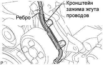
| 28. INSTALL GENERATOR ASSEMBLY |
Confirm that the wire harness of the crankshaft position sensor is secured to the wire harness clamp bracket through the back of the rib of the timing chain cover.
 |
Install the generator with the 2 bolts.
- Момент затяжки:
- 21 Н*м{215 кгс*см, 16 фунт-сила-футов}for bolt A
- 52 Н*м{530 кгс*см, 38 фунт-сила-футов}for bolt B
 |
Install the wire harness clamp.
 |
Install the wire harness clamp bracket with the bolt.
- Момент затяжки:
- 8.4 Н*м{85 кгс*см, 74 фунт-сила-дюймов}
Connect the generator wire with the nut.
- Момент затяжки:
- 9.8 Н*м{100 кгс*см, 7 фунт-сила-футов}
Install the terminal cap.
Connect the generator connector.
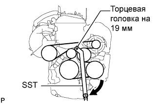
| 29. INSTALL FAN AND GENERATOR V BELT |
Using SST and 19 mm socket wrench, loosen the V-ribbed belt tensioner arm clockwise, then install the fan and generator V belt.
- Специальный инструмент (SST):
- 09216-42010
- ПРИМЕЧАНИЕ:
- Be sure to connect SST and the tools so that they are in line during use.
- When retracting the tensioner, turn it clockwise slowly for 3 seconds or more. Do not apply force rapidly.
- After the tensioner is fully retracted, do not apply force any more than necessary.
 |
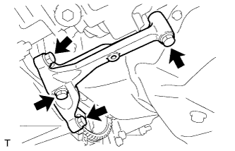
| 30. INSTALL FRONT SUSPENSION MEMBER REINFORCEMENT RH |
Install the reinforcement RH with the 4 bolts.
- Момент затяжки:
- 96 Н*м{989 кгс*см, 71 фунт-сила-футов}
| 31. INSTALL CLUTCH RELEASE CYLINDER ASSEMBLY (for Manual Transaxle) |
Install the clutch release cylinder for E352 (2WD) (see page RAV4_ACA30 RM000001YVM000X_01_0006.html).
Install the clutch release cylinder for E359F (4WD) (see page RAV4_ACA30 RM000001YVM001X_01_0006.html).
| 32. INSTALL TRANSAXLE CONTROL CABLE ASSEMBLY (for Manual Transaxle) |
Install the transaxle control cable for E352 (2WD) (see page RAV4_ACA30 RM000001YVM000X_01_0005.html).
Install the transaxle control cable for E359F (4WD) (see page RAV4_ACA30 RM000001YVM001X_01_0005.html).
| 33. INSTALL TRANSAXLE CONTROL CABLE ASSEMBLY (for Automatic Transaxle) |
Install the transaxle control cable for U241E (2WD) (see page RAV4_ACA30 RM000001SU6001X_01_0005.html).
Install the transaxle control cable for U140F (4WD) (see page RAV4_ACA30 RM000001SU6000X_01_0005.html).
| 34. INSTALL INTAKE MANIFOLD INSULATOR |
Install the intake manifold insulator onto the cylinder block.
 |
| 35. INSTALL INTAKE MANIFOLD |
Install a new gasket into the intake manifold.
 |
Install the intake manifold with the 5 bolts and 2 nuts.
- Момент затяжки:
- 30 Н*м{305 кгс*см, 22 фунт-сила-футов}
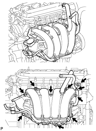 |
Fit the union to check valve hose into the vacuum hose clamp.
Install the wire harness clamp.
Connect the camshaft timing oil control valve connector.
Connect the union to check valve hose to the brake booster.
| 36. INSTALL FUEL DELIVERY PIPE SUB-ASSEMBLY |
Install 4 new insulators into the cylinder head.
 |
Install the 2 delivery pipe spacers onto the cylinder head.
Install the fuel delivery pipe together with the 4 fuel injectors, then temporarily tighten the 2 bolts.
- ПРИМЕЧАНИЕ:
- Be careful not to drop the fuel injectors when installing the fuel delivery pipe.
 |
Check that the fuel injector rotates smoothly.
If the fuel injector does not rotate, replace the O-ring.
Tighten the 2 bolts to the specified torque.
- Момент затяжки:
- 20 Н*м{205 кгс*см, 15 фунт-сила-футов}
 |
Connect the 4 fuel injector connectors.
 |
Install the 2 wire harness clamps.
| 37. CONNECT NO. 2 VENTILATION HOSE |
Connect the ventilation hose to the ventilation valve.
- ПРИМЕЧАНИЕ:
- Make sure that the paint mark and hose clamp are at the correct angle when installing the hose.
 |
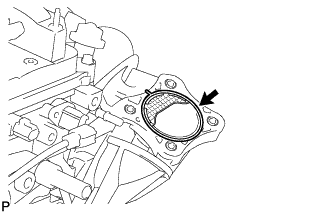
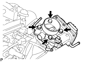
| 38. INSTALL THROTTLE BODY |
Install a new gasket onto the intake manifold.
 |
Install the throttle body and fuel pipe clamp with the 4 bolts.
- Момент затяжки:
- 30 Н*м{305 кгс*см, 22 фунт-сила-футов}
 |
Connect the fuel tube into the clamp.
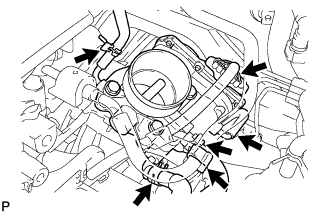 |
Connect the wire harness clamp.
Connect the throttle position sensor and control motor connector.
Connect the No. 1 throttle body hose to the throttle body.
Connect the No. 2 water by-pass hose to the throttle body.
Connect the water by-pass hose to the throttle body.
Connect the purge line hose to the throttle body.
| 39. CONNECT FUEL TUBE |
Connect the fuel main tube.
Push the fuel tube connector until it makes a "click" sound.
Install the fuel pipe clamp.
Install the fuel tube to the fuel hose clamp.
| 40. CONNECT HEATER WATER OUTLET HOSE |
Connect the heater outlet hose to the heater unit.
 |
| 41. CONNECT HEATER WATER INLET HOSE |
Connect the heater inlet hose to the heater unit.
 |
| 42. CONNECT UNION TO CONNECTOR TUBE HOSE (for LHD) |
Connect the 2 union to connector tube hoses to the booster vacuum tube.
 |
| 43. CONNECT UNION TO CONNECTOR TUBE HOSE (for RHD) |
Connect the union to connector tube hose to the booster vacuum tube.
 |
| 44. INSTALL BATTERY CARRIER BRACKET |
Install the battery carrier bracket with the nut and 2 bolts.
- Момент затяжки:
- 20 Н*м{204 кгс*см, 15 фунт-сила-футов}
 |
| 45. INSTALL BATTERY BRACKET REINFORCEMENT |
Install the battery bracket reinforcement with the 2 bolts.
- Момент затяжки:
- 20 Н*м{204 кгс*см, 15 фунт-сила-футов}
 |
| 46. INSTALL FRONT BATTERY CARRIER |
Install the front battery carrier with the 4 bolts.
- Момент затяжки:
- 20 Н*м{204 кгс*см, 15 фунт-сила-футов}
 |
Connect the 2 clamps of the engine wire.
| 47. INSTALL AIR CLEANER CASE SUB-ASSEMBLY |
Connect the air cleaner case to the No. 1 air cleaner inlet.
Install the case with the 3 bolts.
- Момент затяжки:
- 5.0 Н*м{51 кгс*см, 44 фунт-сила-дюймов}
 |
| 48. INSTALL AIR CLEANER FILTER ELEMENT SUB-ASSEMBLY |
| 49. INSTALL AIR CLEANER CAP |
Install the air cleaner filter element onto the air cleaner case.
Insert the hinge part of the air cleaner cap into the air cleaner case, then hang the 2 hook clamps.
 |
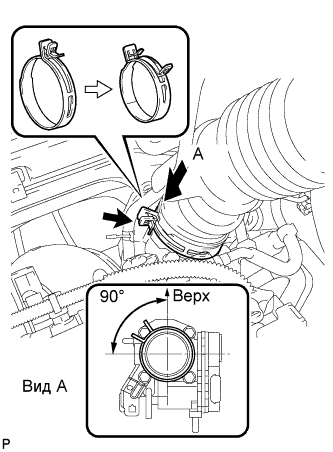
Align the matchmarks of the No. 1 air cleaner hose and throttle body, and then connect the air cleaner hose No. 1 to the throttle body and unfasten the No. 1 air cleaner hose clamp.
- ПРИМЕЧАНИЕ:
- Make sure that the hose clamp is at the correct angle.
 |
Connect the purge line hose to the clamp.
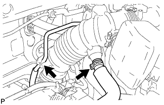 |
Connect the No. 2 ventilation hose to the air cleaner hose.
Install the 4 wire harness clamps.
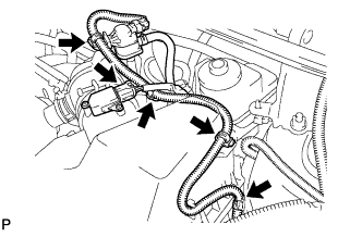 |
Connect the mass air flow meter connector.
| 50. INSTALL PURGE VSV |
Install the purge VSV onto the air cleaner hose.
 |
Connect the 2 purge line hoses to the purge VSV.
 |
Connect the wire harness clamp.
Connect the purge VSV connector.
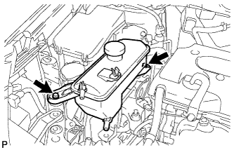
| 51. INSTALL RADIATOR RESERVOIR |
Install the reservoir with the 2 bolts.
- Момент затяжки:
- 5.0 Н*м{51 кгс*см, 44 фунт-сила-дюймов}
 |
| 52. INSTALL RADIATOR ASSEMBLY |
Install the radiator (see page RAV4_ACA30 RM000001X9E000X.html).
| 53. INSTALL BATTERY TRAY |
| 54. INSTALL BATTERY |
Install the battery.
Install the battery clamp with the bolt and nut.
- Момент затяжки:
- 8.5 Н*м{87 кгс*см, 75 фунт-сила-дюймов} for bolt
- 5.0 Н*м{51 кгс*см, 44 фунт-сила-дюймов} for nut
| 55. CONNECT CABLE TO NEGATIVE BATTERY TERMINAL |
| 56. ADD MANUAL TRANSAXLE OIL |
Add manual transaxle oil for E352 (2WD) (see page RAV4_ACA30 RM000001YVM000X_01_0009.html).
Add manual transaxle oil for E359F (4WD) (see page RAV4_ACA30 RM000001YVM001X_01_0009.html).
| 57. ADD AUTOMATIC TRANSAXLE FLUID |
Add automatic transaxle fluid for U241E (2WD) (see page RAV4_ACA30 RM000001STY000X_01_0003.html).
Add automatic transaxle fluid for U140F (4WD) (see page RAV4_ACA30 RM000001STY000X_01_0003.html ).
| 58. CHECK FOR FUEL LEAKS |
Make sure that there are no fuel leaks after performing maintenance on the fuel system.
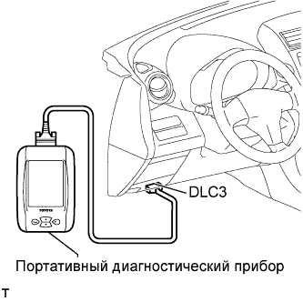
Connect the intelligent tester to the DLC3.
Turn the ignition switch on (IG), and push the intelligent tester main switch ON.
- ПРИМЕЧАНИЕ:
- Do not start the engine.
Select the Active Test mode on the intelligent tester.
- УКАЗАНИЕ:
- Refer to the intelligent tester operator's manual for further details.
Check that there are no leaks from the fuel system.
Turn the ignition switch off.
Disconnect the intelligent tester from the DLC3.
 |
| 59. ADD ENGINE COOLANT |
Tighten the radiator drain cock plug by hand.
Tighten the cylinder block drain cock plug.
- Момент затяжки:
- 12.7 Н*м{130 кгс*см, 10 фунт-сила-футов}
Add TOYOTA Super Long Life Coolant (SLLC) to the radiator reservoir filler opening.
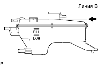
Continue adding TOYOTA SLLC until it is filled to the B line at the base of the reservoir's filler neck.
- УКАЗАНИЕ:
- The B line is the lower edge of the inner wall of the filler neck.
- Standard capacity:
Item Specified Condition A/T 6.5 liters (6.9 US qts, 5.7 Imp. qts) M/T 6.6 liters (7.0 US qts, 5.9 Imp. qts)
- УКАЗАНИЕ:
- TOYOTA vehicles are filled with TOYOTA SLLC at the factory. In order to avoid damage to the engine cooling system and other technical problems, only use TOYOTA SLLC or similar high quality ethylene glycol based non-silicate, non-amine, non-nitrite, non-borate coolant with long-life hybrid organic acid technology (coolant with long-life hybrid organic acid technology consists of a combination of low phosphates and organic acids).
- ПРИМЕЧАНИЕ:
- Never use water as a substitute for engine coolant.
 |
Press the No. 1 and No. 2 radiator hoses several times by hand, and then check the level of the coolant. If the coolant level drops below the B line, add TOYOTA SLLC to the B line.
Install the radiator reservoir cap.
Start the engine and warm it up until the cooling fan operates.
Set the air conditioning as follows while warming up the engine.
Item Specified Condition Manual Air Conditioning System Fan speed: Any setting except OFF
Temperature: Toward WARM
Air conditioning switch: OFFAutomatic Air Conditioning System Temperature: Toward MAX
Air conditioning switch: OFFMaintain the engine speed at 2,000 to 2,500 rpm and warm up the engine until the cooling fan operates.
- ПРИМЕЧАНИЕ:
- Make sure that the radiator reservoir still has some coolant in it.
- Pay attention to the needle of the water temperature meter. Make sure that the needle does not show an abnormally high temperature.
- If there is not enough coolant, the engine may burn out or overheat.
- Immediately after starting the engine, if the radiator reservoir does not have any coolant, perform the following: 1) stop the engine, 2) wait until the coolant has cooled down, and 3) add coolant until the coolant is filled to the B line.
- Run the engine at 2,000 rpm until the coolant level has stabilized.
Press the No. 1 and No. 2 radiator hoses several times by hand to bleed air.
- ПРЕДОСТЕРЕЖЕНИЕ:
When pressing the radiator hoses:- Wear protective gloves.
- Be careful as the radiator hoses are hot.
- Keep your hands away from the radiator fan.
Stop the engine and wait until the coolant cools down to ambient temperature.
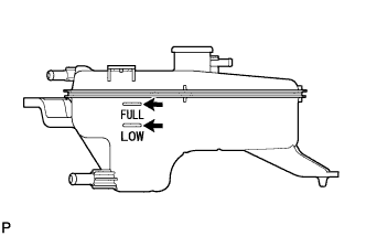
Check that the coolant level is between the FULL and LOW line.
If the coolant level is below the LOW line, repeat all of the procedures above.
If the coolant level is above the FULL line, drain coolant so that the coolant level is between the FULL and LOW line.
 |
| 60. CHECK FOR ENGINE COOLANT LEAKS |
Check for engine coolant leaks (see page RAV4_ACA30 RM0000017W2001X.html).
| 61. CHECK FOR MANUAL TRANSAXLE OIL LEAKS |
| 62. CHECK FOR AUTOMATIC TRANSAXLE FLUID LEAKS |
| 63. INSPECT SHIFT LEVER POSITION |
Переведя рычаг переключения передач из положения P в положение R при включенном зажигании (IG) и нажатой педали тормоза, убедитесь в том, что он перемещается плавно и фиксируется в требуемом положении.
Запустите двигатель и убедитесь, что при переводе рычага из положения N в положение D автомобиль двигается вперед, а при переводе в положение R – назад.
Если результат не удовлетворяет требованиям, проверьте датчик положения паркинга/нейтрали и монтаж рычага переключения передач.
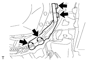
| 64. ADJUST SHIFT LEVER POSITION |
Переведите рычаг переключения передач в положение N.
Сдвиньте крышку регулировочного блока в направлении, показанном на рисунке, и вытяните фиксатор.
 |
Осторожно рукой оттяните тягу троса в направлении задней части автомобиля, чтобы туго натянуть трос.
Вдавите фиксатор в регулировочный блок, чтобы зафиксировать его.
 |
Сдвиньте крышку в направлении, показанном на рисунке.
- ПРИМЕЧАНИЕ:
- Задвигайте крышку за выступ на фиксаторе.
 |
По окончании регулировки проверьте работу механизма.
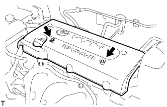
| 65. INSTALL NO. 1 ENGINE COVER |
Install the engine cover with the 2 nuts.
- Момент затяжки:
- 7.0 Н*м{71 кгс*см, 62 фунт-сила-дюймов}
 |
| 66. INSTALL FRONT FENDER APRON RH |
| 67. INSTALL NO. 2 ENGINE UNDER COVER |
| 68. INSTALL NO. 1 ENGINE UNDER COVER |
| 69. INSTALL FRONT WHEEL |
| 70. INSTALL RADIATOR SUPPORT OPENING COVER |
| 71. INSTALL HOOD SUB-ASSEMBLY |
Install the hood (see page RAV4_ACA30 RM00000161X006X_01_0003.html).
Adjust the hood (see page RAV4_ACA30 RM00000138K006X_02_0001.html).
| 72. INSPECT AND ADJUST FRONT WHEEL ALIGNMENT |
Inspect and adjust the front wheel alignment (see page RAV4_ACA30 RM00000227W000X.html).
| 73. RESET MEMORY (for Automatic Transaxle) |
When replacing the engine assembly, perform the RESET MEMORY procedure (A/T initialization ) for U241E (2WD) (see page RAV4_ACA30 RM000000W7F01AX.html) and for U140F (4WD) (see page RAV4_ACA30 RM000000W7F01NX.html).