Sfi System Fuel Pump Control Circuit
DESCRIPTION
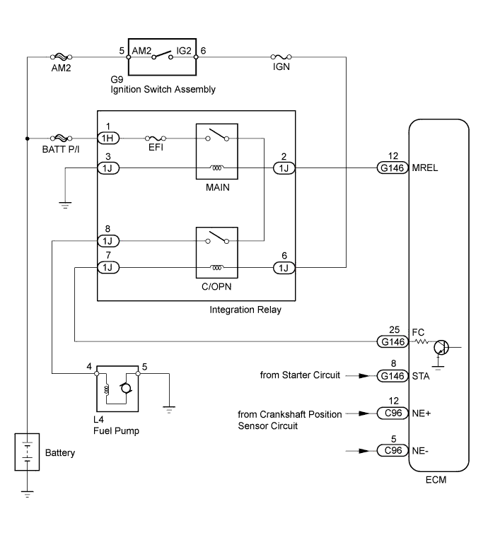
WIRING DIAGRAM
INSPECTION PROCEDURE
PERFORM ACTIVE TEST USING INTELLIGENT TESTER (OPERATE C/OPN RELAY)
INSPECT NO. 1 INTEGRATION RELAY (C/OPN AND MAIN)
CHECK HARNESS AND CONNECTOR (INTEGRATION RELAY [C/OPN] - ECM)
CHECK HARNESS AND CONNECTOR (IGNITION SWITCH ASSEMBLY - INTEGRATION RELAY [C/OPN])
CHECK HARNESS AND CONNECTOR (INTEGRATION RELAY [C/OPN] - FUEL PUMP)
CHECK HARNESS AND CONNECTOR (FUEL PUMP - BODY GROUND)
INSPECT FUEL PUMP
CHECK ECM POWER SOURCE CIRCUIT
SFI SYSTEM - Fuel Pump Control Circuit |
DESCRIPTION
When the engine is cranked, current flows from terminal ST1 of the ignition switch to the starter relay coil and current also flows to terminal STA of the ECM (STA signal).When the STA signal and NE signal are input to the ECM, Tr is turned on, current flows to the coil of the circuit opening relay, the relay switches on, power is supplied to the fuel pump and the fuel pump operates.While the NE signal is generated (engine running), the ECM keeps Tr on (circuit opening relay on) and the fuel pump continues operating.
WIRING DIAGRAM
INSPECTION PROCEDURE
- NOTICE:
- Inspect the fuses for circuits related to this system before performing the following inspection procedure.
| 1.PERFORM ACTIVE TEST USING INTELLIGENT TESTER (OPERATE C/OPN RELAY) |
Connect the intelligent tester to the DLC3.
Turn the ignition switch to ON.
Turn the tester on.
Enter the following menus: Powertrain / Engine and ECT / Active Test / Control the Fuel Pump / Speed.
Check whether the fuel pump operation sound occurs when performing the Active Test on the tester.
- OK:
- Fuel pump operating sound occurs.
| 2.INSPECT NO. 1 INTEGRATION RELAY (C/OPN AND MAIN) |
Inspect the No. 1 integration relay (C/OPN) (HILUX_TGN26 RM000003BLB022X_01_0018.html).
Inspect the integration relay (MAIN) (HILUX_TGN26 RM000003BLB022X_01_0019.html).
| | REPLACE NO. 1 INTEGRATION RELAY (C/OPN AND MAIN) |
|
|
| 3.CHECK HARNESS AND CONNECTOR (INTEGRATION RELAY [C/OPN] - ECM) |
Disconnect the ECM connector.
Remove the integration relay (C/OPN) from the engine room relay block.
Disconnect the integration relay connector.
Measure the resistance according to the value(s) in the table below.
- Standard Resistance (Check for Open):
Tester Connection
| Condition
| Specified Condition
|
1J-7 - G146-25 (FC)
| Always
| Below 1 Ω
|
- Standard Resistance (Check for Short):
Tester Connection
| Condition
| Specified Condition
|
1J-7 or G146-25 (FC) - Body ground
| Always
| 10 kΩ or higher
|
Reconnect the ECM connector.
Reconnect the integration relay connector.
Reinstall the integration relay (C/OPN).
| | REPAIR OR REPLACE HARNESS OR CONNECTOR (INTEGRATION RELAY [C/OPN] - ECM) |
|
|
| 4.CHECK HARNESS AND CONNECTOR (IGNITION SWITCH ASSEMBLY - INTEGRATION RELAY [C/OPN]) |
Remove the integration relay from the engine room relay block.
Disconnect the integration relay connector.
Disconnect the ignition switch assembly connector.
Measure the resistance according to the value(s) in the table below.
- Standard Resistance (Check for Open):
Tester Connection
| Condition
| Specified Condition
|
G9-6 (IG2) - 1J-6
| Always
| Below 1 Ω
|
- Standard Resistance (Check for Short):
Tester Connection
| Condition
| Specified Condition
|
G9-6 (IG2) or 1J-6 - Body ground
| Always
| 10 kΩ or higher
|
Reconnect the ignition switch assembly connector.
Reconnect the integration relay connector.
Reinstall the integration relay.
| | REPAIR OR REPLACE HARNESS OR CONNECTOR (IGNITION SWITCH ASSEMBLY - INTEGRATION RELAY [C/OPN]) |
|
|
| 5.CHECK HARNESS AND CONNECTOR (INTEGRATION RELAY [C/OPN] - FUEL PUMP) |
Disconnect the fuel pump connector.
Remove the integration relay from the engine room relay block.
Disconnect the integration relay connector.
Measure the resistance according to the value(s) in the table below.
- Standard Resistance (Check for Open):
Tester Connection
| Condition
| Specified Condition
|
1J-8 - L4-4
| Always
| Below 1 Ω
|
- Standard Resistance (Check for Short):
Tester Connection
| Condition
| Specified Condition
|
1J-8 or L4-4 - Body ground
| Always
| 10 kΩ or higher
|
Reconnect the integration relay connector.
Reinstall the integration relay.
Reconnect the fuel pump connector.
| | REPAIR OR REPLACE HARNESS OR CONNECTOR (INTEGRATION RELAY [C/OPN] - FUEL PUMP) |
|
|
| 6.CHECK HARNESS AND CONNECTOR (FUEL PUMP - BODY GROUND) |
Disconnect the fuel pump connector.
Measure the resistance according to the value(s) in the table below.
- Standard Resistance:
Tester Connection
| Condition
| Specified Condition
|
L4-5 - Body ground
| Always
| Below 1 Ω
|
Reconnect the fuel pump connector.
| | REPAIR OR REPLACE HARNESS OR CONNECTOR (FUEL PUMP - BODY GROUND) |
|
|
Inspect the fuel pump (HILUX_TGN26 RM000000YLJ01NX.html).
| 8.CHECK ECM POWER SOURCE CIRCUIT |
Check the ECM power source circuit (HILUX_TGN26 RM000002769099X.html).
| | REPAIR OR REPLACE ECM POWER SOURCE CIRCUIT |
|
|