DESCRIPTION
MONITOR DESCRIPTION
CONFIRMATION DRIVING PATTERN
WIRING DIAGRAM
INSPECTION PROCEDURE
CHECK FOR ANY OTHER DTCS OUTPUT (IN ADDITION TO DTC P0171 OR P0172)
CHECK PCV HOSE CONNECTIONS
CHECK AIR INDUCTION SYSTEM
PERFORM ACTIVE TEST USING INTELLIGENT TESTER (CONTROL THE INJECTION VOLUME FOR A/F SENSOR)
READ VALUE USING INTELLIGENT TESTER (COOLANT TEMP)
READ VALUE USING INTELLIGENT TESTER (MAF)
CHECK FUEL PRESSURE
CHECK FOR EXHAUST GAS LEAK
CHECK IGNITION SYSTEM
INSPECT FUEL INJECTOR ASSEMBLY (INJECTION AND VOLUME)
INSPECT AIR FUEL RATIO SENSOR (HEATER RESISTANCE)
CHECK AIR FUEL RATIO SENSOR (POWER SOURCE)
CHECK HARNESS AND CONNECTOR (AIR FUEL RATIO SENSOR - ECM)
REPLACE AIR FUEL RATIO SENSOR
PERFORM CONFIRMATION DRIVING PATTERN
CHECK HARNESS AND CONNECTOR
CHECK WHETHER DTC OUTPUT RECURS
CHECK HARNESS AND CONNECTOR (MASS AIR FLOW METER - ECM)
REPLACE MASS AIR FLOW METER
CONFIRM WHETHER MALFUNCTION HAS BEEN SUCCESSFULLY REPAIRED
CHECK HARNESS AND CONNECTOR (A/F SENSOR - A/F RELAY, A/F RELAY - INTEGRATION RELAY)
INSPECT AIR FUEL RATIO SENSOR HEATER RELAY (A/F)
DTC P0171 System Too Lean (Bank 1) |
DTC P0172 System Too Rich (Bank 1) |
DESCRIPTION
This FFV can be used with E22 to E100; E100 is a fuel with an ethanol concentration of 100%. The short-term fuel trim is fuel compensation information that is used to constantly maintain the air fuel ratio at stoichiometric levels. The signal from the air fuel ratio sensor (sensor 1) indicates whether the air fuel ratio is rich or lean compared to the stoichiometric ratio. This triggers a reduction in the fuel injection volume if the air fuel ratio is rich and an increase in the fuel injection volume if lean. The fuel trim is related to the feedback compensation value, not to the basic injection time. The fuel trim consists of both the short-term (Short FT) and long-term (Long FT) fuel trims, and the alcohol concentration learned value (Alcohol Feedback Value).Factors such as individual engine differences, wear over time and changes in operating environment cause short-term fuel trim to vary from the central value. The long-term fuel trim, which controls overall fuel compensation, compensates for long-term deviations in the fuel trim from the central value caused by the short-term fuel trim compensation. The alcohol concentration learned value (Alcohol Feedback Value) is the injection compensation amount, which the ECM calculates depending on the concentration of alcohol in the fuel. However, in addition to the concentration of alcohol in the fuel, the actual air-fuel ratio deviation due to malfunctions in the engine system is factored into the alcohol concentration learned value.The fuel injection compensation amount, which is used to determine if DTCs P0171 and P0172 are stored, can be calculated by using the following formula.Aggregate fuel trim is equal to the following: Short FT + ((1 + Long FT / 100) x (1 + Alcohol Feedback Value / 100) - 1) x 100Alcohol Concentration
| 22% (E22)
| 46%
| 75%
| 100% (E100)
|
Alcohol Feedback Value
| 8%
| 24%
| 47%
| 70.5%
|
Example:When E22 fuel is used: Aggregate fuel trim = Short FT + ((1 + Long FT / 100) x (1.08) - 1) x 100DTC No.
| DTC Detection Condition
| Trouble Area
|
P0171
| With a warm engine and stable air fuel ratio feedback, the fuel trim is considerably in error to the lean side (2-trip detection logic).
| - Air induction system
- Fuel pressure
- Fuel injector blockage
- Mass air flow meter
- Engine coolant temperature sensor
- Gas leakage from exhaust system
- Open or short in heated oxygen sensor circuit
- Air fuel ratio sensor
- Air fuel ratio sensor heater
- Air fuel ratio sensor heater circuits
- PCV hose connections
- PCV valve and hose
- ECM
- Wire harness or connector
|
P0172
| With a warm engine and stable air fuel ratio feedback, the fuel trim is considerably in error to the rich side (2-trip detection logic).
| - Fuel injector leakage or blockage
- Fuel pressure
- Mass air flow meter
- Engine coolant temperature sensor
- Ignition system
- Gas leakage from exhaust system
- Open or short in heated oxygen sensor circuit
- Air fuel ratio sensor
- Air fuel ratio sensor heater
- Air fuel ratio sensor heater circuits
- Ignition system
- ECM
- Wire harness or connector
|
- HINT:
- When DTC P0171 is stored, the actual air fuel ratio is too lean. When DTC P0172 is stored, the actual air fuel ratio is too rich.
- If the vehicle runs out of fuel, the air fuel ratio becomes lean and DTC P0171 may be stored. The MIL is then illuminated.
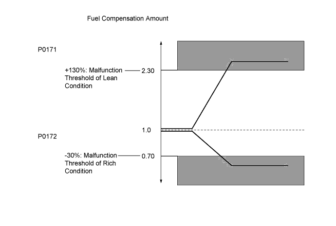
- When the aggregate fuel trim value is within the malfunction threshold values and the engine coolant temperature is higher than 75°C [167°F], the system is functioning normally.
MONITOR DESCRIPTION
During air-fuel ratio feedback, if the short-term fuel trim deviates from 1.0 by a large amount, the alcohol concentration learned value is updated (for example, if the short-term fuel trim is more than 1.0, the alcohol concentration learned value increases), and then the short-term fuel trim deviation is reflected in the long-term fuel trim.Example:When the aggregate fuel trim value is +130% or more, or -30% or less, the ECM interprets this as a fuel system malfunction and stores a DTC.
CONFIRMATION DRIVING PATTERN

- Connect the intelligent tester to the DLC3.
- Turn the ignition switch to ON and turn the tester on [A].
- Clear the DTCs (HILUX_TGN26 RM000000PDK12LX.html).
- Start the engine and warm it up (until the engine coolant temperature is 75°C (167°F) or higher) with all the accessories switched off [B].
- With the engine warmed up, idle the engine for 2 minutes or more [C].
- Drive the vehicle at 60 km/h (37 mph) or more for 20 minutes or more [D].
- CAUTION:
- When performing the confirmation driving pattern, obey all speed limits and traffic laws.
- HINT:
- This step is performed to complete ethanol concentration learning.
- If DTC P0170 or P0172 is output when any of the following conditions is met, it is necessary to complete ethanol concentration learning to meet preconditions.
- The battery has been disconnected and reconnected.
- The DTCs have been cleared.
- Both fuel tank assemblies (for main and sub tanks) have been filled with fuel.
- Drive the vehicle at between 75 and 120 km/h (47 and 75 mph) and at an engine speed of between 1400 and 3200 rpm for 5 minutes or more [E].
- CAUTION:
- When performing the confirmation driving pattern, obey all speed limits and traffic laws.
- Enter the following menus: Powertrain / Engine and ECT / DTC / Pending.
- Read the pending DTC [F].
- HINT:
- If a pending DTC is output, the system is malfunctioning.
WIRING DIAGRAM
Refer to DTC P2195 (HILUX_TGN26 RM000000WC40R3X_07.html).
INSPECTION PROCEDURE
- HINT:
- Read freeze frame data using the intelligent tester. Freeze frame data records the engine condition when malfunctions are detected. When troubleshooting, freeze frame data can help determine if the vehicle was moving or stationary, if the engine was warmed up or not, if the air fuel ratio was lean or rich, and other data from the time the malfunction occurred.
- A low air fuel ratio sensor voltage could be caused by a rich air fuel mixture. Check for conditions that would cause the engine to run rich.
- A high air fuel ratio sensor voltage could be caused by a lean air fuel mixture. Check for conditions that would cause the engine to run lean.
- Sensor 1 refers to the sensor closest to the engine assembly.
- Sensor 2 refers to the sensor farthest away from the engine assembly.
| 1.CHECK FOR ANY OTHER DTCS OUTPUT (IN ADDITION TO DTC P0171 OR P0172) |
Connect the intelligent tester to the DLC3.
Turn the ignition switch to ON.
Turn the tester on.
Enter the following menus: Powertrain / Engine and ECT / DTC.
Read the DTCs.
ResultResult
| Proceed to
|
DTC P0171 or P0172 is output
| A
|
DTC P0171 or P0172 and other DTCs are output
| B
|
- HINT:
- If any DTCs other than P0171 or P0172 are output, troubleshoot those DTCs first.
| 2.CHECK PCV HOSE CONNECTIONS |
Check the PCV hose connections.
- OK:
- PCV hose is connected correctly and is not damaged.
| | REPAIR OR REPLACE PCV HOSE |
|
|
| 3.CHECK AIR INDUCTION SYSTEM |
Check the air induction system for vacuum leakage (HILUX_TGN26 RM000001A3W025X.html).
- OK:
- No leakage from air induction system.
| | REPAIR OR REPLACE AIR INDUCTION SYSTEM |
|
|
| 4.PERFORM ACTIVE TEST USING INTELLIGENT TESTER (CONTROL THE INJECTION VOLUME FOR A/F SENSOR) |
Connect the intelligent tester to the DLC3.
Start the engine.
Turn the intelligent tester on.
Warm up the engine at an engine speed of 2500 rpm for approximately 90 seconds.
Enter the following menus: Powertrain / Engine and ECT / Active Test / Control the Injection Volume for A/F Sensor.
Perform the Control the Injection Volume for A/F Sensor operation with the engine idling (press the RIGHT or LEFT button to change the fuel injection volume).
Monitor the voltage outputs of the Air Fuel Ratio (A/F) sensor and the Heated Oxygen (HO2) sensor (AFS Voltage B1S1 and O2S B1S2) displayed on the intelligent tester.
- HINT:
- The Control the Injection Volume for A/F Sensor operation lowers the fuel injection volume by 12.5% or increases the injection volume by 12.5%.
- Each sensor reacts in accordance with increases and decreases in the fuel injection volume.
- Standard:
Tester Display
(Sensor)
| Injection Volume
| Status
| Voltage
|
AFS Voltage B1S1
(A/F)
| +12.5%
| Rich
| Below 3.1 V
|
-12.5%
| Lean
| Higher than 3.4 V
|
O2S B1S2
(HO2)
| +12.5%
| Rich
| Higher than 0.55 V
|
-12.5%
| Lean
| Below 0.4 V
|
ResultStatus
AFS B1S1
| Status
O2S B1S2
| A/F Condition and
A/F Sensor Condition
| Misfire
| Suspected Trouble Area
| Proceed to
|
Lean/Rich
| Lean/Rich
| Normal
| -
| -
| A
|
Lean
| Lean
| Actual air-fuel ratio lean
| May occur
| - PCV valve and hose
- PCV hose connections
- Injector blockage
- Gas leak from exhaust system
- Air induction system
- Fuel pressure
- Mass Air Flow (MAF) meter
- Engine Coolant Temperature (ECT) sensor
| A
|
Rich
| Rich
| Actual air-fuel ratio rich
| -
| - Injector leak or blockage
- Gas leak from exhaust system
- Ignition system
- Fuel pressure
- MAF meter
- ECT sensor
|
Lean
| Lean/Rich
| A/F sensor malfunction
| -
| - A/F sensor
| B
|
Rich
| Lean/Rich
| A/F sensor malfunction
| -
| - A/F sensor
|
Lean: During Control the Injection Volume for A/F Sensor, the A/F sensor output voltage (AFS) is consistently higher than 3.4 V, and the HO2 sensor output voltage (O2S) is consistently below 0.4 V.
Rich: During Control the Injection Volume for A/F Sensor, the AFS is consistently below 3.1 V, and the O2S is consistently higher than 0.55 V.
Lean/Rich: During Control the Injection Volume for A/F Sensor of the Active Test, the output voltage of the heated oxygen sensor alternates correctly.
- HINT:
- Refer to "Data List / Active Test" [AFS Voltage B1S1 and O2S B1S2] (HILUX_TGN26 RM000000SXS05CX.html).
| 5.READ VALUE USING INTELLIGENT TESTER (COOLANT TEMP) |
Connect the intelligent tester to the DLC3.
Turn the ignition switch to ON and turn the tester on.
Enter the following menus: Powertrain / Engine and ECT / Data List / Primary / Coolant Temp.
Read Coolant Temp twice, when the engine is both cold and warmed up.
- Standard:
- With cold engine: Same as ambient air temperature.
With warm engine: Between 75°C and 100°C (167°F and 212°F).
| 6.READ VALUE USING INTELLIGENT TESTER (MAF) |
Connect the intelligent tester to the DLC3.
Turn the ignition switch to ON.
Turn the intelligent tester on.
Enter the following menus: Powertrain / Engine and ECT / Data List / All Data / MAF and Coolant Temp.
Allow the engine to idle until Coolant Temp reaches 75°C (167°F) or higher.
Read MAF with the engine speed at 3000 rpm.
- Standard:
- Between 10 gm/s and 11.5 gm/s (shift lever: N; A/C: Off).
Check the fuel pressure (HILUX_TGN26 RM000000YL704QX.html).
| | REPAIR OR REPLACE FUEL SYSTEM |
|
|
| 8.CHECK FOR EXHAUST GAS LEAK |
Check for exhaust gas leakage.
- OK:
- No gas leakage.
| | REPAIR OR REPLACE EXHAUST SYSTEM |
|
|
Inspect the ignition system (HILUX_TGN26 RM000000SM604ZX.html).
| | REPAIR OR REPLACE IGNITION SYSTEM |
|
|
| 10.INSPECT FUEL INJECTOR ASSEMBLY (INJECTION AND VOLUME) |
Check the fuel injection and volume (HILUX_TGN26 RM000000YL901AX.html).
| 11.INSPECT AIR FUEL RATIO SENSOR (HEATER RESISTANCE) |
Inspect the air fuel ratio sensor (HILUX_TGN26 RM000001421010X.html).
| 12.CHECK AIR FUEL RATIO SENSOR (POWER SOURCE) |
Disconnect the air fuel ratio sensor connector.
Measure the voltage according to the value(s) in the table below.
- Standard Voltage:
Tester Connection
| Switch Condition
| Specified Condition
|
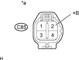
C85-2 (+B) - Body ground
| Ignition switch ON
| 11 to 14 V
|
Text in Illustration*a
| Front view of wire harness connector
(to Air Fuel Ratio Sensor)
|
Reconnect the air fuel ratio sensor connector.
| 13.CHECK HARNESS AND CONNECTOR (AIR FUEL RATIO SENSOR - ECM) |
Disconnect the air fuel ratio sensor connector.
Disconnect the ECM connector.
Measure the resistance according to the value(s) in the table below.
- Standard Resistance (Check for Open):
Tester Connection
| Condition
| Specified Condition
|
C85-1 (HA1A) - C97-6 (HA1A)
| Always
| Below 1 Ω
|
C85-3 (A1A+) - C97-7 (A1A+)
| Always
| Below 1 Ω
|
C85-4 (A1A-) - C97-1 (A1A-)
| Always
| Below 1 Ω
|
- Standard Resistance (Check for Short):
Tester Connection
| Condition
| Specified Condition
|
C85-1 (HA1A) or C97-6 (HA1A) - Body ground
| Always
| 10 kΩ or higher
|
C85-3 (A1A+) or C97-7 (A1A+) - Body ground
| Always
| 10 kΩ or higher
|
C85-4 (A1A-) or C97-1 (A1A-) - Body ground
| Always
| 10 kΩ or higher
|
Reconnect the air fuel ratio sensor connector.
Reconnect the ECM connector.
| | REPAIR OR REPLACE HARNESS OR CONNECTOR |
|
|
| 14.REPLACE AIR FUEL RATIO SENSOR |
Replace the air fuel ratio sensor (HILUX_TGN26 RM00000142300ZX.html).
| 15.PERFORM CONFIRMATION DRIVING PATTERN |
Connect the intelligent tester to the DLC3.
Turn the ignition switch to ON.
Turn the intelligent tester on.
Clear the DTCs (HILUX_TGN26 RM000000PDK12LX.html).
Turn the ignition switch off.
Turn the ignition switch to ON and turn the intelligent tester on.
Start the engine and warm it up.
Drive the vehicle in accordance with the driving pattern described in Confirmation Driving Pattern.
Enter the following menus: Powertrain / Engine and ECT / Trouble Codes.
Read DTCs.
ResultResult
| Proceed to
|
DTC P0171 or P0172 is output
| A
|
DTC is not output
| B
|
| 16.CHECK HARNESS AND CONNECTOR |
Check the connection and terminal contact pressure of connectors and wire harnesses between the mass air flow meter and ECM (HILUX_TGN26 RM000004QR6001X.html).
- HINT:
- Repair any problems.
| 17.CHECK WHETHER DTC OUTPUT RECURS |
Connect the intelligent tester to the DLC3.
Turn the ignition switch to ON.
Turn the intelligent tester on.
Clear the DTCs (HILUX_TGN26 RM000000PDK12LX.html).
Turn the ignition switch off.
Turn the ignition switch to ON and turn the intelligent tester on.
Start the engine and warm it up.
Drive the vehicle in accordance with the driving pattern described in Confirmation Driving Pattern.
Enter the following menus: Powertrain / Engine and ECT / Trouble Codes.
Read DTCs.
ResultResult
| Proceed to
|
DTC P0171 or P0172 is output
| A
|
DTC is not output
| B
|
| 18.CHECK HARNESS AND CONNECTOR (MASS AIR FLOW METER - ECM) |
Disconnect the mass air flow meter connector.
Disconnect the ECM connector.
Measure the resistance according to the value(s) in the table below.
- Standard Resistance (Check for Open):
Tester Connection
| Condition
| Specified Condition
|
C36-3 (VG) - C95-13 (VG)
| Always
| Below 1 Ω
|
C36-2 (E2G) - C95-7 (E2G)
| Always
| Below 1 Ω
|
- Standard Resistance (Check for Short):
Tester Connection
| Condition
| Specified Condition
|
C36-3 (VG) or C95-13 (VG) - Body ground
| Always
| 10 kΩ or higher
|
Reconnect the mass air flow meter connector.
Reconnect the ECM connector.
| | REPAIR OR REPLACE HARNESS OR CONNECTOR |
|
|
| 19.REPLACE MASS AIR FLOW METER |
Replace the mass air flow meter (HILUX_TGN26 RM000000VW602DX.html).
- HINT:
- If the result of the inspection performed in step 6 indicated no problem, proceed to the next step without replacing the mass air flow meter assembly.
| 20.CONFIRM WHETHER MALFUNCTION HAS BEEN SUCCESSFULLY REPAIRED |
Connect the intelligent tester to the DLC3.
Turn the ignition switch to ON.
Turn the intelligent tester on.
Clear the DTCs (HILUX_TGN26 RM000000PDK12LX.html).
Turn the ignition switch off.
Turn the ignition switch to ON and turn the intelligent tester on.
Start the engine and warm it up.
Drive the vehicle in accordance with the driving pattern described in Confirmation Driving Pattern.
Enter the following menus: Powertrain / Engine and ECT / Trouble Codes.
Read DTCs.
ResultResult
| Proceed to
|
DTC is not output
| A
|
DTC P0171 or P0172 is output
| B
|
| 21.CHECK HARNESS AND CONNECTOR (A/F SENSOR - A/F RELAY, A/F RELAY - INTEGRATION RELAY) |
Disconnect the air fuel ratio sensor connector.
Remove the A/F relay from the engine room relay block.
Remove the integration relay from the engine room relay block.
Measure the resistance according to the value(s) in the table below.
- Standard Resistance (Check for Open):
Tester Connection
| Condition
| Specified Condition
|
C85-2 (+B) - A/F relay terminal (5)
| Always
| Below 1 Ω
|
A/F relay terminal (5) - 1H-1
| Always
| Below 1 Ω
|
- Standard Resistance (Check for Short):
Tester Connection
| Condition
| Specified Condition
|
C85-2 (+B) or A/F relay terminal (3) - Body ground
| Always
| 10 kΩ or higher
|
A/F relay terminal (5) or 1H-1 - Body ground
| Always
| 10 kΩ or higher
|
Reconnect the air fuel ratio sensor connector.
Reinstall the integration relay.
Reinstall the A/F relay.
| | REPAIR OR REPLACE HARNESS OR CONNECTOR |
|
|
| 22.INSPECT AIR FUEL RATIO SENSOR HEATER RELAY (A/F) |
Inspect the A/F relay.
Remove the A/F relay from the engine room relay block.
Measure the resistance according to the value(s) in the table below.
- Standard resistance:
Tester Connection
| Condition
| Specified Condition
|
3 - 5
| Always
| 10 kΩ or higher
|
3 - 5
| Always
| Below 1 Ω
(when battery voltage is applied to terminals 1 and 2)
|
| | REPLACE AIR FUEL RATIO SENSOR HEATER RELAY (A/F) |
|
|