DESCRIPTION
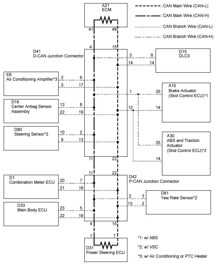
WIRING DIAGRAM
INSPECTION PROCEDURE
CHECK OPEN IN ONE SIDE OF CAN BRANCH WIRE (BRAKE ACTUATOR (SKID CONTROL ECU))
CHECK OPEN IN ONE SIDE OF CAN BRANCH WIRE (BRAKE ACTUATOR (SKID CONTROL ECU) BRANCH WIRE)
CHECK OPEN IN ONE SIDE OF CAN BRANCH WIRE (ABS AND TRACTION ACTUATOR (SKID CONTROL ECU))
CHECK OPEN IN ONE SIDE OF CAN BRANCH WIRE (ABS AND TRACTION ACTUATOR (SKID CONTROL ECU) BRANCH WIRE)
CHECK OPEN IN ONE SIDE OF CAN BRANCH WIRE (AIR CONDITIONING AMPLIFIER)
CHECK OPEN IN ONE SIDE OF CAN BRANCH WIRE (AIR CONDITIONING AMPLIFIER BRANCH WIRE)
CHECK OPEN IN ONE SIDE OF CAN BRANCH WIRE (CENTER AIRBAG SENSOR ASSEMBLY)
CHECK OPEN IN ONE SIDE OF CAN BRANCH WIRE (CENTER AIRBAG SENSOR ASSEMBLY BRANCH WIRE)
CHECK OPEN IN ONE SIDE OF CAN BRANCH WIRE (STEERING SENSOR)
CHECK OPEN IN ONE SIDE OF CAN BRANCH WIRE (STEERING SENSOR BRANCH WIRE)
CHECK OPEN IN ONE SIDE OF CAN BRANCH WIRE (MAIN BODY ECU)
CHECK OPEN IN ONE SIDE OF CAN BRANCH WIRE (MAIN BODY ECU BRANCH WIRE)
CHECK OPEN IN ONE SIDE OF CAN BRANCH WIRE (YAW RATE SENSOR)
CHECK OPEN IN ONE SIDE OF CAN BRANCH WIRE (YAW RATE SENSOR BRANCH WIRE)
CHECK OPEN IN ONE SIDE OF CAN BRANCH WIRE (COMBINATION METER ECU BRANCH WIRE)
CAN COMMUNICATION SYSTEM (for Sedan) - Open in One Side of CAN Branch Line |
DESCRIPTION
If 2 or more ECUs and/or sensors do not appear on the Techstream "Communication Bus Check" screen, one side of the CAN branch wire may be open. (One side of the CAN-H [branch wire] / CAN-L [branch wire] of the ECU and/or sensor is open.)Symptom
| Trouble Area
|
2 or more ECUs and/or sensors do not appear on Techstream "Communication Bus Check" screen
| - Open in side of CAN branch wire
- Brake actuator (skid control ECU)*1
- ABS and traction actuator (skid control ECU)*2
- Steering sensor*2
- Yaw rate sensor*2
- Center airbag sensor assembly
- Air conditioning amplifier*3
- Combination meter ECU
- Main body ECU
- D-CAN junction connector
- P-CAN junction connector
|
- *1: w/ ABS
- *2: w/ VSC
- *3: w/ Air Conditioning or PTC Heater
WIRING DIAGRAM
INSPECTION PROCEDURE
- NOTICE:
- Turn the ignition switch off before measuring the resistances of the CAN main wire and the CAN branch wire.
- After the ignition switch is turned off, check that the key reminder warning system and light reminder warning system are not in operation.
- Before measuring the resistance, leave the vehicle as is for at least 1 minute and do not operate the ignition switch, any other switches or the doors. If doors need to be opened in order to check connectors, open the doors and leave them open.
- HINT:
- Operating the ignition switch, any switches or any doors triggers related ECU and sensor communication with the CAN, which causes resistance variation.
- Perform the following inspection for the ECUs (sensors) which are not displayed on the Techstream. If a malfunction cannot be identified, perform the following inspections for the ECUs (sensors) connected to the CAN communication system.
- Do not remove the power steering ECU and ECM, as they are the end parts of the circuit. If removed, CAN communication will not be possible.
- The open circuit confirmation of the power steering ECU, ECM and main wire is performed in the CHECK CAN BUS LINE procedure of HOW TO PROCEED WITH TROUBLESHOOTING. This inspection only has procedures for checking for an open circuit on one side of the CAN branch wire.
| 1.CHECK OPEN IN ONE SIDE OF CAN BRANCH WIRE (BRAKE ACTUATOR (SKID CONTROL ECU)) |
- HINT:
- For vehicles without ABS, go to step 3.
Disconnect the A15 brake actuator (skid control ECU) connector.
Select "Communication Bus Check" on the Techstream (YARIS_NCP93 RM000001D3E00OX.html).
ResultResult
| Proceed to
|
ABS/VSC/TRC not displayed on Techstream.
| A
|
Several ECUs and sensors other than ABS/VSC/TRC not displayed on Techstream.
| B
|
| 2.CHECK OPEN IN ONE SIDE OF CAN BRANCH WIRE (BRAKE ACTUATOR (SKID CONTROL ECU) BRANCH WIRE) |
Measure the resistance according to the value(s) in the table below.
- HINT:
- The resistance must be measured after the A15 brake actuator (skid control ECU) connector is disconnected.
- Standard Resistance:
Tester Connection
| Switch Condition
| Specified Condition
|
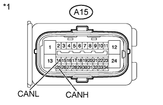
A15-25 (CANH) - A15-14 (CANL)
| Ignition switch off
| 54 to 69 Ω
|
Text in Illustration*1
| Front view of wire harness connector
(to Brake Actuator (Skid Control ECU))
|
| | REPAIR OR REPLACE CAN BRANCH WIRE CONNECTED TO BRAKE ACTUATOR (SKID CONTROL ECU (CAN-H, CAN-L)) |
|
|
| 3.CHECK OPEN IN ONE SIDE OF CAN BRANCH WIRE (ABS AND TRACTION ACTUATOR (SKID CONTROL ECU)) |
- HINT:
- For vehicles without VSC, go to step 5.
Disconnect the A30 ABS and traction actuator (skid control ECU) connector.
Select "Communication Bus Check" on the Techstream (YARIS_NCP93 RM000001D3E00OX.html).
ResultResult
| Proceed to
|
ABS/VSC/TRC not displayed on Techstream.
| A
|
Several ECUs and sensors other than ABS/VSC/TRC not displayed on Techstream.
| B
|
| 4.CHECK OPEN IN ONE SIDE OF CAN BRANCH WIRE (ABS AND TRACTION ACTUATOR (SKID CONTROL ECU) BRANCH WIRE) |
Measure the resistance according to the value(s) in the table below.
- HINT:
- The resistance must be measured after the A30 ABS and traction actuator (skid control ECU) connector is disconnected.
- Standard Resistance:
Tester Connection
| Switch Condition
| Specified Condition
|
A30-25 (CANH) - A30-14 (CANL)
| Ignition switch off
| 54 to 69 Ω
|
Text in Illustration*1
| Front view of wire harness connector
(to ABS and Traction Actuator (Skid Control ECU))
|
| | REPAIR OR REPLACE CAN BRANCH WIRE CONNECTED TO ABS AND TRACTION ACTUATOR (SKID CONTROL ECU (CAN-H, CAN-L)) |
|
|
| 5.CHECK OPEN IN ONE SIDE OF CAN BRANCH WIRE (AIR CONDITIONING AMPLIFIER) |
- HINT:
- For vehicles without air conditioning or PTC heater, go to step 7.
Disconnect the E8 air conditioning amplifier connector.
Select "Communication Bus Check" on the Techstream (YARIS_NCP93 RM000001D3E00OX.html).
ResultResult
| Proceed to
|
Air conditioner not displayed on Techstream.
| A
|
Several ECUs and sensors other than air conditioner not displayed on Techstream.
| B
|
| 6.CHECK OPEN IN ONE SIDE OF CAN BRANCH WIRE (AIR CONDITIONING AMPLIFIER BRANCH WIRE) |
Measure the resistance according to the value(s) in the table below.
- HINT:
- The resistance must be measured after the E8 air conditioning amplifier connector is disconnected.
- Standard Resistance:
Tester Connection
| Switch Condition
| Specified Condition
|
E8-2 (TX+) - E8-3 (TX-)
| Ignition switch off
| 54 to 69 Ω
|
Text in Illustration*1
| Front view of wire harness connector
(to Air Conditioning Amplifier)
|
| | REPAIR OR REPLACE CAN BRANCH WIRE CONNECTED TO AIR CONDITIONING AMPLIFIER (CAN-H, CAN-L) |
|
|
| 7.CHECK OPEN IN ONE SIDE OF CAN BRANCH WIRE (CENTER AIRBAG SENSOR ASSEMBLY) |
Disconnect the D16 center airbag sensor assembly connector.
Select "Communication Bus Check" on the Techstream (YARIS_NCP93 RM000001D3E00OX.html).
ResultResult
| Proceed to
|
SRS airbag not displayed on Techstream.
| A
|
Several ECUs and sensors other than SRS airbag not displayed on Techstream.
| B
|
| 8.CHECK OPEN IN ONE SIDE OF CAN BRANCH WIRE (CENTER AIRBAG SENSOR ASSEMBLY BRANCH WIRE) |
Measure the resistance according to the value(s) in the table below.
- HINT:
- The resistance must be measured after the D16 center airbag sensor assembly connector is disconnected.
- Standard Resistance:
Tester Connection
| Switch Condition
| Specified Condition
|
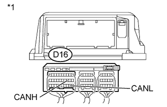
D16-13 (CANH) - D16-22 (CANL)
| Ignition switch off
| 54 to 69 Ω
|
Text in Illustration*1
| Rear view of wire harness connector
(to Center Airbag Sensor Assembly)
|
| | REPAIR OR REPLACE CAN BRANCH WIRE CONNECTED TO CENTER AIRBAG SENSOR ASSEMBLY (CAN-H, CAN-L) |
|
|
| 9.CHECK OPEN IN ONE SIDE OF CAN BRANCH WIRE (STEERING SENSOR) |
- HINT:
- For vehicles without VSC, go to step 11.
Disconnect the D80 steering sensor connector.
Select "Communication Bus Check" on the Techstream (YARIS_NCP93 RM000001D3E00OX.html).
ResultResult
| Proceed to
|
Steering angle sensor not displayed on Techstream.
| A
|
Several ECUs and sensors other than steering angle sensor not displayed on Techstream.
| B
|
| 10.CHECK OPEN IN ONE SIDE OF CAN BRANCH WIRE (STEERING SENSOR BRANCH WIRE) |
Measure the resistance according to the value(s) in the table below.
- HINT:
- The resistance must be measured after the D80 steering sensor connector is disconnected.
- Standard Resistance:
Tester Connection
| Switch Condition
| Specified Condition
|
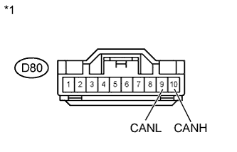
D80-10 (CANH) - D80-9 (CANL)
| Ignition switch off
| 54 to 69 Ω
|
Text in Illustration*1
| Front view of wire harness connector
(to Steering Sensor)
|
| | REPAIR OR REPLACE CAN BRANCH WIRE CONNECTED TO STEERING SENSOR (CAN-H, CAN-L) |
|
|
| 11.CHECK OPEN IN ONE SIDE OF CAN BRANCH WIRE (MAIN BODY ECU) |
Disconnect the D33 main body ECU connector.
Select "Communication Bus Check" on the Techstream (YARIS_NCP93 RM000001D3E00OX.html).
ResultResult
| Proceed to
|
Integrated J/B not displayed on Techstream.
| A
|
Several ECUs and sensors other than integrated J/B not displayed on Techstream.
| B
|
| 12.CHECK OPEN IN ONE SIDE OF CAN BRANCH WIRE (MAIN BODY ECU BRANCH WIRE) |
Measure the resistance according to the value(s) in the table below.
- HINT:
- The resistance must be measured after the D33 main body ECU connector is disconnected.
- Standard Resistance:
Tester Connection
| Switch Condition
| Specified Condition
|
D33-23 (CANH) - D33-22 (CANL)
| Ignition switch off
| 54 to 69 Ω
|
Text in Illustration*1
| Rear view of wire harness connector
(to Main Body ECU)
|
| | REPAIR OR REPLACE CAN BRANCH WIRE CONNECTED TO MAIN BODY ECU (CAN-H, CAN-L) |
|
|
| 13.CHECK OPEN IN ONE SIDE OF CAN BRANCH WIRE (YAW RATE SENSOR) |
- HINT:
- For vehicles without VSC, go to step 15.
Disconnect the D81 yaw rate sensor connector.
Select "Communication Bus Check" on the Techstream (YARIS_NCP93 RM000001D3E00OX.html).
ResultResult
| Proceed to
|
Yaw Rate / Deceleration Sensor not displayed on Techstream.
| A
|
Several ECUs and sensors other than Yaw Rate / Deceleration Sensor not displayed on Techstream.
| B
|
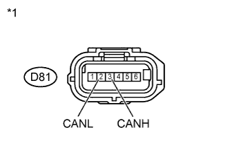
| 14.CHECK OPEN IN ONE SIDE OF CAN BRANCH WIRE (YAW RATE SENSOR BRANCH WIRE) |
Measure the resistance according to the value(s) in the table below.
- HINT:
- The resistance must be measured after the D81 yaw rate sensor connector is disconnected.
- Standard Resistance:
Tester Connection
| Switch Condition
| Specified Condition
|
D81-3 (CANH) - D81-2 (CANL)
| Ignition switch off
| 54 to 69 Ω
|
Text in Illustration*1
| Front view of wire harness connector
(to Yaw Rate Sensor)
|
| | REPAIR OR REPLACE CAN BRANCH WIRE CONNECTED TO YAW RATE SENSOR (CAN-H, CAN-L) |
|
|
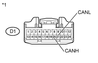
| 15.CHECK OPEN IN ONE SIDE OF CAN BRANCH WIRE (COMBINATION METER ECU BRANCH WIRE) |
Disconnect the D1 combination meter ECU connector.
Measure the resistance according to the value(s) in the table below.
- Standard Resistance:
Tester Connection
| Switch Condition
| Specified Condition
|
D1-20 (CANH) - D1-21 (CANL)
| Ignition switch off
| 54 to 69 Ω
|
Text in Illustration*1
| Front view of wire harness connector
(to Combination Meter ECU)
|
| | REPAIR OR REPLACE CAN BRANCH WIRE CONNECTED TO COMBINATION METER (CAN-H, CAN-L) |
|
|