Cruise Control System (For Hatchback) Cruise Control Switch Circuit
DESCRIPTION
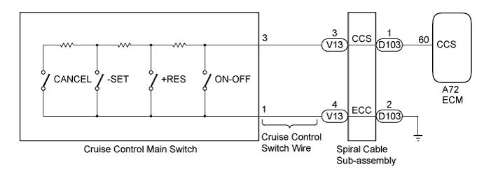
WIRING DIAGRAM
INSPECTION PROCEDURE
READ VALUE USING TECHSTREAM (CRUISE CONTROL MAIN SWITCH)
INSPECT CRUISE CONTROL MAIN SWITCH
INSPECT CRUISE CONTROL SWITCH WIRE
INSPECT SPIRAL CABLE SUB-ASSEMBLY
CHECK HARNESS AND CONNECTOR (SPIRAL CABLE SUB-ASSEMBLY - ECM AND BODY GROUND)
CRUISE CONTROL SYSTEM (for Hatchback) - Cruise Control Switch Circuit |
DESCRIPTION
This circuit sends a signal to the ECM depending on the cruise control main switch condition. The battery supplies positive (+) battery voltage to the cruise control main switch. Terminal 60 (CCS) of the ECM receives the voltage which varies according to the switch condition.
WIRING DIAGRAM
INSPECTION PROCEDURE
| 1.READ VALUE USING TECHSTREAM (CRUISE CONTROL MAIN SWITCH) |
Using the Techstream, read the Data List (YARIS_NCP93 RM0000044B200NX.html).
Cruise ControlTester Display
| Measurement Item/Range
| Normal Condition
| Diagnostic Note
|
Main SW M-CPU
| Cruise control main switch (Main CPU) / OFF or ON
| OFF: Cruise control main switch off
ON: Cruise control main switch on
| -
|
Cancel Switch
| CANCEL switch signal / OFF or ON
| OFF: CANCEL switch off
ON: CANCEL switch on
| -
|
SET/COAST Switch
| -SET switch signal / OFF or ON
| OFF: -SET switch off
ON: -SET switch on
| -
|
RES/ACC Switch
| +RES switch signal / OFF or ON
| OFF: +RES switch off
ON: +RES switch on
| -
|
- OK:
- The display is as specified in the normal condition column.
| 2.INSPECT CRUISE CONTROL MAIN SWITCH |
Inspect the cruise control main switch (YARIS_NCP93 RM000001Z6E041X.html).
| 3.INSPECT CRUISE CONTROL SWITCH WIRE |
Remove the cruise control switch wire.
Measure the resistance according to the value(s) in the table below.
- Standard Resistance:
Tester Connection
| Condition
| Specified Condition
|
V13-3 (CCS) - 3 (CCS)
| Always
| Below 1 Ω
|
V13-4 (ECC) - 1 (ECC)
|
Text in Illustration*a
| Front view of wire harness connector
(to Spiral Cable Sub-assembly)
|
*b
| Front view of wire harness connector
(to Cruise Control Switch)
|
| | REPLACE CRUISE CONTROL SWITCH WIRE |
|
|
| 4.INSPECT SPIRAL CABLE SUB-ASSEMBLY |
Inspect the spiral cable sub-assembly (YARIS_NCP93 RM000000UWB07GX.html).
| 5.CHECK HARNESS AND CONNECTOR (SPIRAL CABLE SUB-ASSEMBLY - ECM AND BODY GROUND) |
Disconnect the D103 spiral cable sub-assembly connector.
Disconnect the A72 ECM connector.
Measure the resistance according to the value(s) in the table below.
- Standard Resistance:
Tester Connection
| Condition
| Specified Condition
|
D103-1 (CCS) - A72-60 (CCS)
| Always
| Below 1 Ω
|
D103-2 (ECC) - Body ground
|
D103-1 (CCS) - Body ground
| Always
| 10 kΩ or higher
|
| | REPAIR OR REPLACE HARNESS OR CONNECTOR |
|
|