Cooling Fan System (For Sedan) Cooling Fan Circuit
TECHNICAL DESCRIPTION
WIRING DIAGRAM
INSPECTION PROCEDURE
CHECK INTEGRATION RELAY
CHECK ENGINE ROOM RELAY BLOCK
INSPECT INTEGRATION RELAY
INSPECT FAN NO. 2 RELAY
INSPECT COOLING FAN RESISTOR
CHECK WIRE HARNESS AND CONNECTOR (FAN NO. 2 RELAY - BODY GROUND)
CHECK WIRE HARNESS AND CONNECTOR (COOLING FAN RESISTOR - BODY GROUND)
CHECK WIRE HARNESS AND CONNECTOR (FAN NO. 2 RELAY - COOLING FAN RESISTOR)
CHECK COOLING FAN MOTOR
CHECK WIRE HARNESS AND CONNECTOR (COOLING FAN MOTOR - INTEGRATION RELAY)
CHECK WIRE HARNESS AND CONNECTOR (COOLING FAN MOTOR - FAN NO. 2 RELAY)
CHECK WIRE HARNESS AND CONNECTOR (ENGINE ROOM RELAY BLOCK - ECM)
COOLING FAN SYSTEM (for Sedan) - Cooling Fan Circuit |
TECHNICAL DESCRIPTION
To control the cooling fans, the ECM turns on or off the cooling fan relays based on the engine coolant temperature, air conditioning switch, refrigerant pressure, engine speed and vehicle speed signals.The ECM turns on or off the fan relays to switch the cooling fan motor circuit between the series circuit and parallel circuit, controlling the cooling fan motor speed in 2 steps.
WIRING DIAGRAM
Refer to System Diagram (YARIS_NCP93 RM000001E6N00BX.html).
INSPECTION PROCEDURE
- NOTICE:
- Inspect the fuses for circuits related to this system before performing the following inspection procedure.
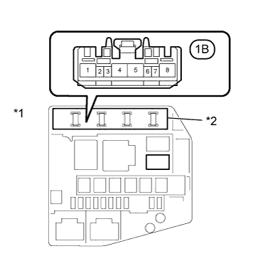
| 1.CHECK INTEGRATION RELAY |
Remove the INTEGRATION RELAY from the engine room relay block.
Measure the voltage according to the value(s) in the table below.
- Standard Voltage:
Tester Connection
| Condition
| Specified Condition
|
INTEGRATION RELAY Connector 1B-5 - Body ground
| Always
| 11 to 14V
|
Text in Illustration*1
| Engine Room Relay Block
|
*2
| INTEGRATION RELAY
|
Reinstall the INTEGRATION RELAY.
| | REPAIR OR REPLACE HARNESS AND CONNECTOR |
|
|
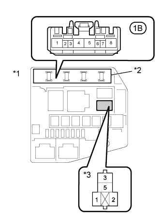
| 2.CHECK ENGINE ROOM RELAY BLOCK |
Remove the INTEGRATION RELAY and FAN No. 2 relay from the engine room relay block.
Turn the Ignition switch to ON.
Measure the voltage according to the value(s) in the table below.
- Standard Voltage:
Tester Connection
| Condition
| Specified Condition
|
INTEGRATION RELAY Connector 1B-6 - Body ground
| Ignition switch ON
| 11 to 14V
|
FAN No. 2 relay terminal 2 - Body ground
| Ignition switch ON
| 11 to 14V
|
Text in Illustration*1
| Engine Room Relay Block
|
*2
| INTEGRATION RELAY
|
*3
| FAN No. 2Relay
|
Reinstall the INTEGRATION RELAY and FAN No. 2 relay.
| | REPAIR OR REPLACE HARNESS AND CONNECTOR |
|
|
| 3.INSPECT INTEGRATION RELAY |
Inspect the INTEGRATION RELAY (YARIS_NCP93 RM000001CMR032X.html).
| | REPLACE INTEGRATION RELAY |
|
|
| 4.INSPECT FAN NO. 2 RELAY |
Inspect the FAN No. 2 relay (YARIS_NCP93 RM0000017WF02JX.html).
| 5.INSPECT COOLING FAN RESISTOR |
Inspect the cooling fan resistor (YARIS_NCP93 RM000003FVD00XX.html).
| | REPLACE COOLING FAN RESISTOR |
|
|
| 6.CHECK WIRE HARNESS AND CONNECTOR (FAN NO. 2 RELAY - BODY GROUND) |
Remove the FAN No. 2 relay from the engine room main relay block.
Measure the resistance according to the value(s) in the table below.
- Standard Resistance:
Tester Connection
| Condition
| Specified Condition
|
FAN No. 2 relay terminal 5 - Body ground
| Always
| Below 1 Ω
|
Reinstall the FAN No. 2 relay.
| | REPAIR OR REPLACE HARNESS AND CONNECTOR |
|
|
| 7.CHECK WIRE HARNESS AND CONNECTOR (COOLING FAN RESISTOR - BODY GROUND) |
Disconnect the cooling fan resistor connector.
Measure the resistance according to the value(s) in the table below.
- Standard Resistance:
Tester Connection
| Condition
| Specified Condition
|
A14-1 (-) - Body ground
| Always
| Below 1 Ω
|
Connect the cooling fan resistor connector.
| | REPAIR OR REPLACE HARNESS AND CONNECTOR |
|
|
| 8.CHECK WIRE HARNESS AND CONNECTOR (FAN NO. 2 RELAY - COOLING FAN RESISTOR) |
Disconnect the cooling fan resistor connector.
Remove the FAN No. 2 relay from the engine room relay block.
Measure the resistance according to the value(s) in the table below.
- Standard Resistance (Check for Open):
Tester Connection
| Condition
| Specified Condition
|
FAN No. 2 relay terminal 4 - A14-2 (+)
| Always
| Below 1 Ω
|
- Standard Resistance (Check for Short):
Tester Connection
| Condition
| Specified Condition
|
A14-2 (+) or FAN No. 2 relay terminal 4 - Body ground
| Always
| 10 kΩ or higher
|
Reinstall the FAN No. 2 relay.
Reconnect the cooling fan resistor connector.
| | REPAIR OR REPLACE HARNESS AND CONNECTOR |
|
|
| 9.CHECK COOLING FAN MOTOR |
Inspect the cooling fan motor (YARIS_NCP93 RM000001E4S01RX.html).
| 10.CHECK WIRE HARNESS AND CONNECTOR (COOLING FAN MOTOR - INTEGRATION RELAY) |
Disconnect the cooling fan motor connector.
Remove the INTEGRATION RELAY from the engine room relay block.
Measure the resistance according to the value(s) in the table below.
- Standard Resistance (Check for Open):
Tester Connection
| Condition
| Specified Condition
|
A8-2 - INTEGRATION RELAY Connector 1B-8
| Always
| Below 1 Ω
|
- Standard Resistance (Check for Short):
Tester Connection
| Condition
| Specified Condition
|
A8-2 - INTEGRATION RELAY Connector 1B-8
| Always
| 10 kΩ or higher
|
Reinstall the INTEGRATION RELAY.
Reconnect the cooling fan motor connector.
| | REPAIR OR REPLACE HARNESS AND CONNECTOR |
|
|
| 11.CHECK WIRE HARNESS AND CONNECTOR (COOLING FAN MOTOR - FAN NO. 2 RELAY) |
Disconnect the cooling fan motor connector.
Remove the FAN No. 2 relay from the engine room relay block.
Measure the resistance according to the value(s) in the table below.
- Standard Resistance (Check for Open):
Tester Connection
| Condition
| Specified Condition
|
A8-1 - FAN No. 2 relay terminal 3
| Always
| Below 1 Ω
|
- Standard Resistance (Check for Short):
Tester Connection
| Condition
| Specified Condition
|
A8-1 or FAN No. 2 relay terminal 3 - Body ground
| Always
| 10 kΩ or higher
|
Reinstall the FAN No. 2 relay.
Reconnect the cooling fan motor connector.
| | REPAIR OR REPLACE HARNESS AND CONNECTOR |
|
|
| 12.CHECK WIRE HARNESS AND CONNECTOR (ENGINE ROOM RELAY BLOCK - ECM) |
Remove the INTEGRATION RELAY and FAN No. 2 relay from the engine room relay block.
Disconnect the ECM connector.
Measure the resistance according to the value(s) in the table below.
- Standard Resistance (Check for Open):
Tester Connection
| Condition
| Specified Condition
|
A21-22 (FAN2) - FAN No. 2 relay terminal 1
| Always
| Below 1 Ω
|
A21-21 (FAN) - INTEGRATION RELAY Connector 1B-8
| Always
| Below 1 Ω
|
- Standard Resistance (Check for Short):
Tester Connection
| Condition
| Specified Condition
|
A21-22 (FAN2) or FAN No. 2 relay terminal 1 - Body ground
| Always
| 10 kΩ or higher
|
A21-21 (FAN) or INTEGRATION RELAY Connector 1B-8 - Body ground
| Always
| 10 kΩ or higher
|
Reconnect the ECM connector.
Reinstall the INTEGRATION RELAY and FAN No. 2 relay.
| | REPAIR OR REPLACE HARNESS AND CONNECTOR |
|
|