DESCRIPTION
WIRING DIAGRAM
INSPECTION PROCEDURE
READ VALUE USING TECHSTREAM (STARTER SIGNAL)
INSPECT ECM (STSW TERMINAL VOLTAGE)
INSPECT RELAY (ST RELAY VOLTAGE)
CHECK HARNESS AND CONNECTOR (PARK/NEUTRAL POSITION SWITCH - ECM)
CHECK HARNESS AND CONNECTOR (CLUTCH PEDAL SWITCH - ECM)
INSPECT PARK/NEUTRAL POSITION SWITCH
CHECK HARNESS AND CONNECTOR (IGNITION SWITCH ASSEMBLY - PARK/NEUTRAL POSITION SWITCH)
CHECK HARNESS AND CONNECTOR (PARK/NEUTRAL POSITION SWITCH - ECM)
CHECK HARNESS AND CONNECTOR (PARK/NEUTRAL POSITION SWITCH - ST RELAY AND ECM)
INSPECT PARK/NEUTRAL POSITION SWITCH (POWER SOURCE)
CHECK HARNESS AND CONNECTOR (PARK/NEUTRAL POSITION SWITCH - ST RELAY AND ECM)
INSPECT RELAY (ST CUT RELAY)
CHECK HARNESS AND CONNECTOR (PARK/NEUTRAL POSITION SWITCH - ST CUT RELAY, MAIN BODY ECU)
CHECK HARNESS AND CONNECTOR (ECM - ST CUT RELAY AND MAIN BODY ECU)
CHECK HARNESS AND CONNECTOR (ST CUT RELAY - BODY GROUND)
INSPECT FUSE (IGN FUSE)
CHECK HARNESS AND CONNECTOR (ST CUT RELAY - INTEGRATION RELAY (IG2 RELAY))
INSPECT CLUTCH PEDAL SWITCH
CHECK HARNESS AND CONNECTOR (IGNITION SWITCH ASSEMBLY - CLUTCH PEDAL SWITCH)
CHECK HARNESS AND CONNECTOR (CLUTCH PEDAL SWITCH - ECM)
CHECK HARNESS AND CONNECTOR (CLUTCH PEDAL SWITCH - ST RELAY AND ECM)
INSPECT FUSE (AM2 NO. 2 FUSE)
INSPECT IGNITION SWITCH ASSEMBLY
CHECK HARNESS AND CONNECTOR (AM2 TERMINAL VOLTAGE)
CHECK HARNESS AND CONNECTOR (ECM - MAIN BODY ECU)
INSPECT ST RELAY (VOLTAGE)
INSPECT RELAY (ST RELAY)
INSPECT ST RELAY (VOLTAGE)
CHECK HARNESS AND CONNECTOR (ST RELAY - BODY GROUND)
CHECK HARNESS AND CONNECTOR (ST RELAY - STARTER)
CHECK HARNESS AND CONNECTOR (STARTER - BATTERY)
SFI SYSTEM - Cranking Holding Function Circuit |
DESCRIPTION
The cranking holding control system keeps energizing the ST relay after the ECM detects the starter signal (STSW signal) from the ignition switch*1 or main body ECU*2 until the ECM performs a judgment of "Engine started". Furthermore, the ECM outputs an accessory cut signal (ACCR signal) to the ACC CUT relay during cranking to prevent flickering of the combination meter, clock, audio system, and other areas.When the ECM detects the STSW signal, the ECM outputs the ST relay drive signal (STAR signal) to the ST relay through the clutch pedal switch*3 or park/neutral position switch*4, and then the engine is cranked. When the ECM receives a stable engine speed signal (NE signal) (more specifically, when the NE signal reaches a predetermined value), the ECM stops outputting the STAR signal. Also, the ECM monitors the ST relay operating conditions based on the STA terminal voltage status.*1: w/o smart key system*2: w/ smart key system*3: for manual transaxle models*4: for automatic transaxle models
WIRING DIAGRAM
INSPECTION PROCEDURE
| 1.READ VALUE USING TECHSTREAM (STARTER SIGNAL) |
Connect the Techstream to the DLC3.
Turn the ignition switch to ON.
Turn the Techstream ON.
Enter the following menus: Powertrain / Engine and ECT / Data List / Starter Signal.
Check the result when the ignition switch is turned to ON and START.
- OK:
Ignition Switch Position
| Techstream Display (Starter Signal)
|
ON
| Close (Starter signal off)
|
START
| Open (Starter signal on)
|
- Result:
| 2.INSPECT ECM (STSW TERMINAL VOLTAGE) |
Disconnect the ECM connector.
Turn the ignition switch to ON.
Measure the voltage according to the value(s) in the table below.
- Standard Voltage:
Tester Connection
| Switch Condition
| Specified Condition
|
A50-14 (STSW) - Body ground
| Ignition switch ON
| Below 1 V
|
A50-14 (STSW) - Body ground
| Ignition switch START
| 9 to 13 V
|
- Result:
Result
| Proceed to
|
OK
| A
|
NG (w/o smart key system)
| B
|
NG (w/ smart key system)
| C
|
Reconnect the ECM connector.
- HINT:
- DTCs related to the communication with other computers may be set due to this inspection. Clear those DTCs after inspection.
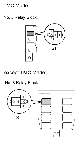
| 3.INSPECT RELAY (ST RELAY VOLTAGE) |
Remove the ST relay from the No. 5 relay block (TMC made).
Remove the ST relay from the No. 8 relay block (except TMC made).
Turn the ignition switch to ON.
Measure the voltage according to the value(s) in the table below.
- Standard Voltage:
TMC MadeTester Connection
| Switch Condition
| Specified Condition
|
ST relay terminal 1 - Body ground
| Ignition switch ON
| Below 1 V
|
ST relay terminal 1 - Body ground
| Ignition switch START
| 9 to 13 V
|
except TMC MadeTester Connection
| Switch Condition
| Specified Condition
|
ST relay terminal 2 - Body ground
| Ignition switch ON
| Below 1 V
|
ST relay terminal 2 - Body ground
| Ignition switch START
| 9 to 13 V
|
- Result:
Result
| Proceed to
|
OK (for automatic transaxle models)
| A
|
OK (for manual transaxle models)
| B
|
NG (for automatic transaxle models)
| C
|
NG (for manual transaxle models)
| D
|
Reinstall the ST relay.
| 4.CHECK HARNESS AND CONNECTOR (PARK/NEUTRAL POSITION SWITCH - ECM) |
Disconnect the ECM connector.
Disconnect the park/neutral position switch assembly connector.
Measure the resistance according to the value(s) in the table below.
- Standard Resistance (Check for Open):
Tester Connection
| Condition
| Specified Condition
|
B88-5 (L) - A50-48(STA)
| Always
| Below 1 Ω
|
- Standard Resistance (Check for Short):
Tester Connection
| Condition
| Specified Condition
|
B88-5 (L) or A50-48(STA) - Body ground
| Always
| 10 kΩ or higher
|
Reconnect the ECM connector.
Reconnect the park/neutral position switch assembly connector.
| | REPAIR OR REPLACE HARNESS OR CONNECTOR (PARK/NEUTRAL POSITION SWITCH - ECM) |
|
|
| 5.CHECK HARNESS AND CONNECTOR (CLUTCH PEDAL SWITCH - ECM) |
Disconnect the ECM connector.
Disconnect the clutch pedal switch connector.
Measure the resistance according to the value(s) in the table below.
- Standard Resistance (Check for Open):
Tester Connection
| Condition
| Specified Condition
|
A5-1 - A50-48 (STA)
| Always
| Below 1 Ω
|
- Standard Resistance (Check for Short):
Tester Connection
| Condition
| Specified Condition
|
A5-1 or A50-48 (STA) - Body ground
| Always
| 10 kΩ or higher
|
Reconnect the ECM connector.
Reconnect the clutch pedal switch connector.
| | REPAIR OR REPLACE HARNESS OR CONNECTOR (CLUTCH PEDAL SWITCH - ECM) |
|
|
| 6.INSPECT PARK/NEUTRAL POSITION SWITCH |
Inspect the park/neutral position switch (COROLLA_ZRE142 RM00000191B03DX.html).
- Result:
Result
| Proceed to
|
OK (w/o smart key system)
| A
|
OK (w/ smart key system)
| B
|
NG
| C
|
| 7.CHECK HARNESS AND CONNECTOR (IGNITION SWITCH ASSEMBLY - PARK/NEUTRAL POSITION SWITCH) |
Disconnect the park/neutral position switch connector.
Disconnect the ignition switch assembly connector.
Measure the resistance according to the value(s) in the table below.
- Standard Resistance (Check for Open):
Tester Connection
| Condition
| Specified Condition
|
E4-8 (ST2) (+) - B88-4 (B) (-)
| Always
| Below 1 Ω
|
E4-8 (ST2) (-) - B88-4 (B) (+)
| Always
| 10 kΩ or higher
|
- Standard Resistance (Check for Short):
Tester Connection
| Condition
| Specified Condition
|
E4-8 (ST2) or B88-4 (B) - Body ground
| Always
| 10 kΩ or higher
|
- HINT:
- When measuring the resistance, it is necessary to reverse the positive (+) and negative (-) tester probes because there is a diode in the wire harness.
Reconnect the park/neutral position switch connector.
Reconnect the ignition switch assembly connector.
| | REPAIR OR REPLACE HARNESS OR CONNECTOR (IGNITION SWITCH ASSEMBLY - PARK/NEUTRAL POSITION SWITCH) |
|
|
| 8.CHECK HARNESS AND CONNECTOR (PARK/NEUTRAL POSITION SWITCH - ECM) |
Disconnect the ECM connector.
Disconnect the park/neutral position switch connector.
Measure the resistance according to the value(s) in the table below.
- Standard Resistance (Check for Open):
Tester Connection
| Condition
| Specified Condition
|
B88-4 (B) - A50-25 (STAR)
| Always
| Below 1 Ω
|
- Standard Resistance (Check for Short):
Tester Connection
| Condition
| Specified Condition
|
B88-4 (B) or A50-25 (STAR) - Body ground
| Always
| 10 kΩ or higher
|
Reconnect the ECM connector.
Reconnect the park/neutral position switch connector.
| | REPAIR OR REPLACE HARNESS OR CONNECTOR (PARK/NEUTRAL POSITION SWITCH - ECM) |
|
|
| 9.CHECK HARNESS AND CONNECTOR (PARK/NEUTRAL POSITION SWITCH - ST RELAY AND ECM) |
Disconnect the park/neutral position switch connector.
Remove the ST relay from the No. 5 relay block (TMC made).
Remove the ST relay from the No. 8 relay block (except TMC made).
Disconnect the ECM connector.
Measure the resistance according to the value(s) in the table below.
- Standard Resistance (Check for Open):
TMC MadeTester Connection
| Condition
| Specified Condition
|
B88-5 (L) - ST relay terminal 1
| Always
| Below 1 Ω
|
except TMC MadeTester Connection
| Condition
| Specified Condition
|
B88-5 (L) - ST relay terminal 2
| Always
| Below 1 Ω
|
- Standard Resistance (Check for Short):
TMC MadeTester Connection
| Condition
| Specified Condition
|
B88-5 (L), ST relay terminal 1 or A50-48 (STA) - Body ground
| Always
| 10 kΩ or higher
|
except TMC MadeTester Connection
| Condition
| Specified Condition
|
B88-5 (L), ST relay terminal 2 or A50-48 (STA) - Body ground
| Always
| 10 kΩ or higher
|
Reconnect the park/neutral position switch connector.
Reinstall the ST relay.
Reconnect the ECM connector.
| | REPAIR OR REPLACE HARNESS OR CONNECTOR (PARK/NEUTRAL POSITION SWITCH - ST RELAY AND/OR ECM) |
|
|
| 10.INSPECT PARK/NEUTRAL POSITION SWITCH (POWER SOURCE) |
Disconnect the park/neutral position switch connector.
Move the shift lever to the P or N position.
Measure the voltage according to the value(s) in the table below.
- Standard Voltage:
Tester Connection
| Switch Condition
| Specified Condition
|
B88-4 (B) - Body ground
| Ignition switch ON
| Below 1 V
|
B88-4 (B) - Body ground
| Ignition switch START
| 9 to 13 V
|
Reconnect the park/neutral position switch connector.
| 11.CHECK HARNESS AND CONNECTOR (PARK/NEUTRAL POSITION SWITCH - ST RELAY AND ECM) |
Disconnect the park/neutral position switch connector.
Remove the ST relay from the No. 8 relay block.
Disconnect the ECM connector.
Measure the resistance according to the value(s) in the table below.
- Standard Resistance (Check for Open):
Tester Connection
| Condition
| Specified Condition
|
B88-5 (L) - ST relay terminal 2
| Always
| Below 1 Ω
|
- Standard Resistance (Check for Short):
Tester Connection
| Condition
| Specified Condition
|
B88-5 (L), ST relay terminal 2 and A50-48 (STA) - Body ground
| Always
| 10 kΩ or higher
|
Reconnect the ECM connector.
Reinstall the ST relay.
Reconnect the park/neutral position switch connector.
| | REPAIR OR REPLACE HARNESS OR CONNECTOR (PARK/NEUTRAL POSITION SWITCH - ST RELAY AND/OR ECM) |
|
|
| 12.INSPECT RELAY (ST CUT RELAY) |
Remove the ST CUT relay from the No. 8 relay block.
Measure the resistance according to the value(s) in the table below.
- Standard Resistance:
Tester Connection
| Condition
| Specified Condition
|
3 - 5
| Always
| 10 kΩ or higher
|
3 - 5
| Apply battery voltage between terminal 1 and 2
| Below 1 Ω
|
| | REPLACE RELAY (ST CUT RELAY) |
|
|
| 13.CHECK HARNESS AND CONNECTOR (PARK/NEUTRAL POSITION SWITCH - ST CUT RELAY, MAIN BODY ECU) |
Disconnect the park/neutral position switch connector.
Remove the ST CUT relay from the No. 8 relay block.
Disconnect the main body ECU connector.
Measure the resistance according to the value(s) in the table below.
- Standard Resistance (Check for Open):
Tester Connection
| Condition
| Specified Condition
|
B88-4 (B) - ST CUT relay terminal 3
| Always
| Below 1 Ω
|
B88-4 (B) - E52-3 (STR)
| Always
| Below 1 Ω
|
- Standard Resistance (Check for Short):
Tester Connection
| Condition
| Specified Condition
|
B88-4 (B), ST CUT relay terminal 3 and E52-3 (STR) - Body ground
| Always
| 10 kΩ or higher
|
Reconnect the main body ECU connector.
Reinstall the ST CUT relay.
Reconnect the park/neutral position switch connector.
| | REPAIR OR REPLACE HARNESS OR CONNECTOR (PARK/NEUTRAL POSITION SWITCH - ST CUT RELAY, MAIN BODY ECU) |
|
|
| 14.CHECK HARNESS AND CONNECTOR (ECM - ST CUT RELAY AND MAIN BODY ECU) |
Disconnect the ECM connector.
Remove the ST CUT relay from the No. 8 relay block.
Disconnect the main body ECU connector.
Measure the resistance according to the value(s) in the table below.
- Standard Resistance (Check for Open):
Tester Connection
| Condition
| Specified Condition
|
A50-25 (STAR) - ST CUT relay terminal 5
| Always
| Below 1 Ω
|
A50-25 (STAR) - E52-14 (STR2)
| Always
| Below 1 Ω
|
- Standard Resistance (Check for Short):
Tester Connection
| Condition
| Specified Condition
|
A50-25 (STAR), ST CUT relay terminal 5 and E52-14 (STR2) - Body ground
| Always
| 10 kΩ or higher
|
Reconnect the main body ECU connector.
Reinstall the ST CUT relay.
Reconnect the ECM connector.
| | REPAIR OR REPLACE HARNESS OR CONNECTOR (ECM - ST CUT RELAY AND/OR MAIN BODY ECU) |
|
|
| 15.CHECK HARNESS AND CONNECTOR (ST CUT RELAY - BODY GROUND) |
Remove the ST CUT relay from the No. 8 relay block.
Measure the resistance according to the value(s) in the table below.
- Standard Resistance:
Tester Connection
| Condition
| Specified Condition
|
ST CUT relay terminal 1 - Body ground
| Always
| Below 1 Ω
|
Reinstall the ST CUT relay.
| | REPAIR OR REPLACE HARNESS OR CONNECTOR (ST CUR RELAY - BODY GROUND) |
|
|
| 16.INSPECT FUSE (IGN FUSE) |
Remove the IGN fuse from the instrument panel junction block.
Measure the resistance according to the value(s) in the table below.
- Standard Resistance:
Tester Connection
| Condition
| Specified Condition
|
IGN fuse
| Always
| Below 1 Ω
|
Reinstall the IGN fuse.
| | CHECK FOR SHORTS IN ALL HARNESSES AND CONNECTORS CONNECTED TO FUSE AND REPLACE FUSE |
|
|
| 17.CHECK HARNESS AND CONNECTOR (ST CUT RELAY - INTEGRATION RELAY (IG2 RELAY)) |
Remove the ST CUT relay from the No. 8 relay block.
Remove the integration relay from the engine room relay block.
Disconnect the integration relay connector.
Measure the resistance according to the value(s) in the table below.
- Standard Resistance (Check for Open):
Tester Connection
| Condition
| Specified Condition
|
ST CUT relay terminal 2 - 1A-4
| Always
| Below 1 Ω
|
- Standard Resistance (Check for Short):
Tester Connection
| Condition
| Specified Condition
|
ST CUT relay terminal 2 or 1A-4 - Body ground
| Always
| 10 kΩ or higher
|
Reconnect the integration relay connector.
Reinstall the integration relay.
Reinstall the ST CUT relay.
| | REPAIR OR REPLACE HARNESS OR CONNECTOR (ST CUT RELAY - INTEGRATION RELAY (IG2 RELAY)) |
|
|
| 18.INSPECT CLUTCH PEDAL SWITCH |
Inspect the clutch pedal switch (COROLLA_ZRE142 RM00000241M01MX.html).
| 19.CHECK HARNESS AND CONNECTOR (IGNITION SWITCH ASSEMBLY - CLUTCH PEDAL SWITCH) |
Disconnect the clutch pedal switch connector.
Disconnect the ignition switch assembly connector.
Measure the resistance according to the value(s) in the table below.
- Standard Resistance (Check for Open):
Tester Connection
| Condition
| Specified Condition
|
E4-8 (ST2) (+) - A5-2 (-)
| Always
| Below 1 Ω
|
E4-8 (ST2) (-) - A5-2 (+)
| Always
| 10 kΩ or higher
|
- Standard Resistance (Check for Short):
Tester Connection
| Condition
| Specified Condition
|
E4-8 (ST2) or A5-2 - Body ground
| Always
| 10 kΩ or higher
|
- HINT:
- When measuring the resistance, it is necessary to reverse the positive (+) and negative (-) tester probes because there is a diode in the wire harness.
Reconnect the clutch pedal switch connector.
Reconnect the ignition switch assembly connector.
| | REPAIR OR REPLACE HARNESS OR CONNECTOR (IGNITION SWITCH ASSEMBLY - CLUTCH PEDAL SWITCH) |
|
|
| 20.CHECK HARNESS AND CONNECTOR (CLUTCH PEDAL SWITCH - ECM) |
Disconnect the ECM connector.
Disconnect the clutch pedal switch connector.
Measure the resistance according to the value(s) in the table below.
- Standard Resistance (Check for Open):
Tester Connection
| Condition
| Specified Condition
|
A5-2 - A50-25 (STAR)
| Always
| Below 1 Ω
|
- Standard Resistance (Check for Short):
Tester Connection
| Condition
| Specified Condition
|
A5-2 or A50-25 (STAR) - Body ground
| Always
| 10 kΩ or higher
|
Reconnect the ECM connector.
Reconnect the clutch pedal switch connector.
| | REPAIR OR REPLACE HARNESS OR CONNECTOR (CLUTCH PEDAL SWITCH - ECM) |
|
|
| 21.CHECK HARNESS AND CONNECTOR (CLUTCH PEDAL SWITCH - ST RELAY AND ECM) |
Disconnect the clutch pedal switch connector.
Remove the ST relay from the No. 5 relay block (TMC made).
Remove the ST relay from the No. 8 relay block (except TMC made).
Disconnect the ECM connector.
Measure the resistance according to the value(s) in the table below.
- Standard Resistance (Check for Open):
TMC MadeTester Connection
| Condition
| Specified Condition
|
ST relay terminal 1 - A5-1
| Always
| Below 1 Ω
|
except TMC MadeTester Connection
| Condition
| Specified Condition
|
ST relay terminal 2 - A5-1
| Always
| Below 1 Ω
|
- Standard Resistance (Check for Short):
TMC MadeTester Connection
| Condition
| Specified Condition
|
A5-1, ST relay terminal 1 or A50-48 (STA) - Body ground
| Always
| 10 kΩ or higher
|
except TMC MadeTester Connection
| Condition
| Specified Condition
|
A5-1, ST relay terminal 2 or A50-48 (STA) - Body ground
| Always
| 10 kΩ or higher
|
Reconnect the clutch pedal switch connector.
Reinstall the ST relay.
Reconnect the ECM connector.
| | REPAIR OR REPLACE HARNESS OR CONNECTOR (CLUTCH PEDAL SWITCH - ST RELAY AND/OR ECM) |
|
|
| 22.INSPECT FUSE (AM2 NO. 2 FUSE) |
Remove the AM2 No. 2 fuse from the engine room relay block.
Measure the resistance according to the value(s) in the table below.
- Standard Resistance:
Tester Connection
| Condition
| Specified Condition
|
AM2 No. 2 fuse
| Always
| Below 1 Ω
|
Reinstall the AM2 No. 2 fuse.
| | CHECK FOR SHORTS IN ALL HARNESSES AND CONNECTORS CONNECTED TO FUSE AND REPLACE FUSE |
|
|
| 23.INSPECT IGNITION SWITCH ASSEMBLY |
Inspect the ignition switch assembly (COROLLA_ZRE142 RM0000026VF01KX.html).
| 24.CHECK HARNESS AND CONNECTOR (AM2 TERMINAL VOLTAGE) |
Disconnect the ignition switch assembly connector.
Measure the voltage according to the value(s) in the table below.
- Standard Voltage:
Tester Connection
| Condition
| Specified Condition
|
E4-7 (AM2) - Body ground
| Always
| 11 to 14 V
|
Reconnect the ignition switch assembly connector.
| | REPAIR OR REPLACE HARNESS OR CONNECTOR (BATTERY - IGNITION SWITCH ASSEMBLY) |
|
|
| OK |
|
|
|
| REPAIR OR REPLACE HARNESS OR CONNECTOR (ECM - IGNITION SWITCH) |
|
| 25.CHECK HARNESS AND CONNECTOR (ECM - MAIN BODY ECU) |
Disconnect the ECM connector.
Disconnect the main body ECU connector.
Measure the resistance according to the value(s) in the table below.
- Standard Resistance (Check for Open):
Tester Connection
| Condition
| Specified Condition
|
A50-14 (STSW) - E52-4 (STSW)
| Always
| Below 1 Ω
|
- Standard Resistance (Check for Short):
Tester Connection
| Condition
| Specified Condition
|
A50-14 (STSW) or E52-4 (STSW) - Body ground
| Always
| 10 kΩ or higher
|
Reconnect the ECM connector.
Reconnect the main body ECU connector.
| | REPAIR OR REPLACE HARNESS OR CONNECTOR (ECM - MAIN BODY ECU) |
|
|
| 26.INSPECT ST RELAY (VOLTAGE) |
Remove the ST relay from the No. 5 relay block (TMC made).
Remove the ST relay from the No. 8 relay block (except TMC made).
Turn the ignition switch to ON.
Measure the voltage according to the value(s) in the table below.
- Standard Voltage:
TMC MadeTester Connection
| Switch Condition
| Specified Condition
|
ST relay terminal 1 - Body ground
| Ignition switch ON
| Below 1 V
|
ST relay terminals 1 - Body ground
| Ignition switch START
| 9 to 13 V
|
except TMC MadeTester Connection
| Switch Condition
| Specified Condition
|
ST relay terminal 2 - Body ground
| Ignition switch ON
| Below 1 V
|
ST relay terminal 2 - Body ground
| Ignition switch START
| 9 to 13 V
|
- Result:
Result
| Proceed to
|
OK
| A
|
NG (for automatic transaxle models)
| B
|
NG (for manual transaxle models)
| C
|
Reinstall the ST relay.
| | REPAIR OR REPLACE HARNESS OR CONNECTOR (ST RELAY - PARK/NEUTRAL POSITION SWITCH) |
|
|
| | REPAIR OR REPLACE HARNESS OR CONNECTOR (ST RELAY - CLUTCH PEDAL SWITCH) |
|
|
| 27.INSPECT RELAY (ST RELAY) |
Inspect the ST relay (COROLLA_ZRE142 RM000003D3A009X_01_0001.html).
| 28.INSPECT ST RELAY (VOLTAGE) |
Remove the ST relay from the No. 5 relay block (TMC made).
Remove the ST relay from the No. 8 relay block (except TMC made).
Turn the ignition switch to ON.
Measure the voltage according to the value(s) in the table below.
- Standard Voltage:
Tester Connection
| Switch Condition
| Specified Condition
|
ST relay terminal 5 - Body ground
| Ignition switch ON
| 11 to 14 V
|
Reinstall the ST relay.
| | REPAIR OR REPLACE HARNESS OR CONNECTOR (BATTERY - ST RELAY) |
|
|
| 29.CHECK HARNESS AND CONNECTOR (ST RELAY - BODY GROUND) |
Remove the ST relay from the No. 5 relay block (TMC made).
Remove the ST relay from the No. 8 relay block (except TMC made).
Measure the resistance according to the value(s) in the table below.
- Standard Resistance (Check for Open):
TMC MadeTester Connection
| Condition
| Specified Condition
|
ST relay terminal 2 - Body ground
| Always
| Below 1 Ω
|
except TMC MadeTester Connection
| Condition
| Specified Condition
|
ST relay terminal 1 - Body ground
| Always
| Below 1 Ω
|
Reinstall the ST relay.
| | REPAIR OR REPLACE HARNESS OR CONNECTOR (ST RELAY - BODY GROUND) |
|
|
| 30.CHECK HARNESS AND CONNECTOR (ST RELAY - STARTER) |
Remove the ST relay from the No. 5 relay block (TMC made).
Remove the ST relay from the No. 8 relay block (except TMC made).
Disconnect the starter connector.
Measure the resistance according to the value(s) in the table below.
- Standard Resistance (Check for Open):
Tester Connection
| Condition
| Specified Condition
|
ST relay terminal 3 - B8-1
| Always
| Below 1 Ω
|
- Standard Resistance (Check for Short):
Tester Connection
| Condition
| Specified Condition
|
ST relay terminal 3 or B8-1 - Body ground
| Always
| 10 kΩ or higher
|
Reconnect the starter connector.
Reinstall the ST relay.
| | REPAIR OR REPLACE HARNESS OR CONNECTOR (ST RELAY - STARTER) |
|
|
| 31.CHECK HARNESS AND CONNECTOR (STARTER - BATTERY) |
Disconnect the cable from the negative (-) battery terminal.
Disconnect the cable from the positive (+) battery terminal.
Disconnect the starter connector.
Measure the resistance according to the value(s) in the table below.
- Standard Resistance (Check for Open):
Tester Connection
| Condition
| Specified Condition
|
B4-1 - Positive (+) battery terminal
| Always
| Below 1 Ω
|
- Standard Resistance (Check for Short):
Tester Connection
| Condition
| Specified Condition
|
B4-1 or Positive (+) battery terminal - Body ground
| Always
| 10 kΩ or higher
|
Reconnect the starter connector.
Reconnect the cable to the positive (+) battery terminal.
Reconnect the cable to the negative (-) battery terminal.
| | REPAIR OR REPLACE HARNESS OR CONNECTOR (STARTER - BATTERY) |
|
|