DESCRIPTION
WIRING DIAGRAM
INSPECTION PROCEDURE
CHECK HARNESS AND CONNECTOR (ECM - BODY GROUND)
INSPECT ECM (IGSW VOLTAGE)
INSPECT FUSE (EFI MAIN FUSE)
INSPECT FUSE (EFI NO. 1 FUSE)
INSPECT INTEGRATION RELAY (EFI MAIN RELAY)
CHECK HARNESS AND CONNECTOR (INTEGRATION RELAY (EFI MAIN RELAY) - ECM)
CHECK HARNESS AND CONNECTOR (INTEGRATION RELAY (EFI MAIN RELAY) - BATTERY)
CHECK HARNESS AND CONNECTOR (INTEGRATION RELAY (EFI MAIN RELAY) - BODY GROUND)
INSPECT FUSE (IGN FUSE)
INSPECT FUSE (IG2 FUSE)
INSPECT INTEGRATION RELAY (IG2 RELAY)
CHECK HARNESS AND CONNECTOR (INTEGRATION RELAY (IG2 RELAY) - ECM)
CHECK HARNESS AND CONNECTOR (INTEGRATION RELAY (IG2 RELAY) - BATTERY)
CHECK HARNESS AND CONNECTOR (INTEGRATION RELAY (IG2 RELAY) - BODY GROUND)
CHECK HARNESS AND CONNECTOR (INTEGRATION RELAY (IG2 RELAY) - IGNITION SWITCH ASSEMBLY)
INSPECT IGNITION SWITCH ASSEMBLY
INSPECT FUSE (AM2 NO. 2 FUSE)
CHECK HARNESS AND CONNECTOR (MAIN BODY ECU - INTEGRATION RELAY (IG2 RELAY))
INSPECT FUSE (AM2 NO. 2 FUSE)
CHECK HARNESS AND CONNECTOR (AM2 VOLTAGE)
SFI SYSTEM - ECM Power Source Circuit |
DESCRIPTION
When the ignition switch is turned to the ON, battery voltage is applied to IGSW of the ECM. The output signal from the MREL terminal of the ECM causes a current to flow to the coil, closing the contacts of the integration relay (EFI MAIN relay) and supplying power to either terminals +B and +B2 of the ECM.
WIRING DIAGRAM
INSPECTION PROCEDURE
| 1.CHECK HARNESS AND CONNECTOR (ECM - BODY GROUND) |
Disconnect the ECM connector.
Measure the resistance according to the value(s) in the table below.
- Standard Resistance:
Tester Connection
| Condition
| Specified Condition
|
B31-105 (E1) - Body ground
| Always
| Below 1 Ω
|
Reconnect the ECM connector.
| | REPAIR OR REPLACE HARNESS OR CONNECTOR (ECM - BODY GROUND) |
|
|
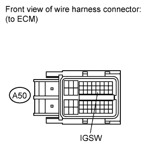
| 2.INSPECT ECM (IGSW VOLTAGE) |
Disconnect the ECM connector.
Turn the ignition switch to ON.
Measure the voltage according to the value(s) in the table below.
- Standard Voltage:
Tester Connection
| Switch Condition
| Specified Condition
|
A50-27 (IGSW) - Body ground
| Ignition switch ON
| 11 to 14 V
|
Reconnect the ECM connector.
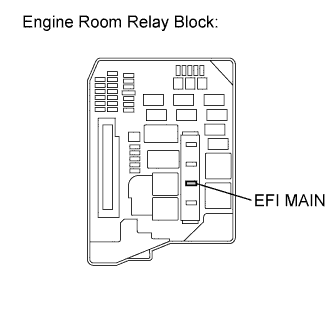
| 3.INSPECT FUSE (EFI MAIN FUSE) |
Remove the EFI MAIN fuse from the engine room relay block.
Measure the resistance according to the value(s) in the table below.
- Standard Resistance:
Tester Connection
| Condition
| Specified Condition
|
EFI MAIN fuse
| Always
| Below 1 Ω
|
Reinstall the EFI MAIN fuse.
| | CHECK FOR SHORTS IN ALL HARNESSES AND CONNECTORS CONNECTED TO FUSE AND REPLACE FUSE |
|
|
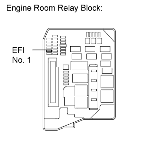
| 4.INSPECT FUSE (EFI NO. 1 FUSE) |
Remove the EFI No. 1 fuse from the engine room relay block.
Measure the resistance according to the value(s) in the table below.
- Standard Resistance:
Tester Connection
| Condition
| Specified Condition
|
EFI No. 1 fuse
| Always
| Below 1 Ω
|
Reinstall the EFI No. 1 fuse.
| | CHECK FOR SHORTS IN ALL HARNESSES AND CONNECTORS CONNECTED TO FUSE AND REPLACE FUSE |
|
|
| 5.INSPECT INTEGRATION RELAY (EFI MAIN RELAY) |
Inspect the integration relay (EFI MAIN relay) (COROLLA_ZRE142 RM000001CMR04AX.html).
| 6.CHECK HARNESS AND CONNECTOR (INTEGRATION RELAY (EFI MAIN RELAY) - ECM) |
Remove the integration relay from the engine room relay block.
Disconnect the integration relay connector.
Disconnect the ECM connector.
Measure the resistance according to the value(s) in the table below.
- Standard Resistance (Check for Open):
Tester Connection
| Condition
| Specified Condition
|
1B-4 - A50-1 (+B2)
| Always
| Below 1 Ω
|
1B-4 - A50-2 (+B)
| Always
| Below 1 Ω
|
1B-2 - A50-44 (MREL)
| Always
| Below 1 Ω
|
- Standard Resistance (Check for Short):
Tester Connection
| Condition
| Specified Condition
|
1B-4 or A50-1 (+B2) - Body ground
| Always
| 10 kΩ or higher
|
1B-4 or A50-2 (+B) - Body ground
| Always
| 10 kΩ or higher
|
1B-2 or A50-44 (MREL) - Body ground
| Always
| 10 kΩ or higher
|
Reconnect the ECM connector.
Reconnect the integration relay connector.
Reinstall the integration relay.
| | REPAIR OR REPLACE HARNESS OR CONNECTOR (INTEGRATION RELAY (EFI MAIN RELAY) - ECM) |
|
|
| 7.CHECK HARNESS AND CONNECTOR (INTEGRATION RELAY (EFI MAIN RELAY) - BATTERY) |
Remove the integration relay from the engine room relay block.
Disconnect the integration relay connector.
Disconnect the negative battery terminal.
Disconnect the positive battery terminal.
Measure the resistance according to the value(s) in the table below.
- Standard Resistance (Check for Open):
Tester Connection
| Condition
| Specified Condition
|
1E-1 - Battery positive terminal
| Always
| Below 1 Ω
|
- Standard Resistance (Check for Short):
Tester Connection
| Condition
| Specified Condition
|
1E-1 or Battery positive terminal - Body ground
| Always
| 10 kΩ or higher
|
Reconnect the integration relay connector.
Reinstall the integration relay.
Reconnect the positive battery terminal.
Reconnect the negative battery terminal.
| | REPAIR OR REPLACE HARNESS OR CONNECTOR (INTEGRATION RELAY (EFI MAIN RELAY) - BATTERY) |
|
|
| 8.CHECK HARNESS AND CONNECTOR (INTEGRATION RELAY (EFI MAIN RELAY) - BODY GROUND) |
Remove the integration relay from the engine room relay block.
Disconnect the integration relay connector.
Measure the resistance according to the value(s) in the table below.
- Standard Resistance:
Tester Connection
| Condition
| Specified Condition
|
1B-3 - Body ground
| Always
| Below 1 Ω
|
Reconnect the integration relay connector.
Reinstall the integration relay.
| | REPAIR OR REPLACE HARNESS OR CONNECTOR (INTEGRATION RELAY (EFI MAIN RELAY) - BODY GROUND) |
|
|
| 9.INSPECT FUSE (IGN FUSE) |
Remove the IGN fuse from the instrument panel junction block.
Measure the resistance according to the value(s) in the table below.
- Standard Resistance:
Tester Connection
| Condition
| Specified Condition
|
IGN fuse
| Always
| Below 1 Ω
|
Reinstall the IGN fuse.
| | CHECK FOR SHORTS IN ALL HARNESSES AND CONNECTORS CONNECTED TO FUSE AND REPLACE FUSE |
|
|
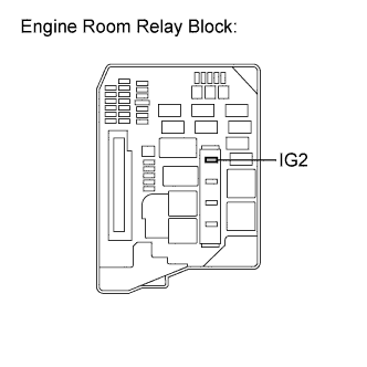
| 10.INSPECT FUSE (IG2 FUSE) |
Remove the IG2 fuse from the engine room relay block.
Measure the resistance according to the value(s) in the table below.
- Standard Resistance:
Tester Connection
| Condition
| Specified Condition
|
IG2 fuse
| Always
| Below 1 Ω
|
Reinstall the IG2 fuse.
| | CHECK FOR SHORTS IN ALL HARNESSES AND CONNECTORS CONNECTED TO FUSE AND REPLACE FUSE |
|
|
| 11.INSPECT INTEGRATION RELAY (IG2 RELAY) |
Inspect the integration relay (IG2 relay) (COROLLA_ZRE142 RM000001CMR04AX.html).
| 12.CHECK HARNESS AND CONNECTOR (INTEGRATION RELAY (IG2 RELAY) - ECM) |
Disconnect the ECM connector.
Remove the integration relay from the engine room relay block.
Disconnect the integration relay connector.
Measure the resistance according to the value(s) in the table below.
- Standard Resistance (Check for Open):
Tester Connection
| Condition
| Specified Condition
|
1A-4 - A50-27 (IGSW)
| Always
| Below 1 Ω
|
- Standard Resistance (Check for Short):
Tester Connection
| Condition
| Specified Condition
|
1A-4 or A50-27 (IGSW) - Body ground
| Always
| 10 kΩ or higher
|
Reconnect the ECM connector.
Reconnect the integration relay connector.
Reinstall the integration relay.
| | REPAIR OR REPLACE HARNESS OR CONNECTOR (INTEGRATION RELAY (IG2 RELAY) - ECM) |
|
|
| 13.CHECK HARNESS AND CONNECTOR (INTEGRATION RELAY (IG2 RELAY) - BATTERY) |
Remove the integration relay from the engine room relay block.
Disconnect the integration relay connector.
Disconnect the negative battery terminal.
Disconnect the positive battery terminal.
Measure the resistance according to the value(s) in the table below.
- Standard Resistance (Check for Open):
Tester Connection
| Condition
| Specified Condition
|
1E-1 - Battery positive terminal
| Always
| Below 1 Ω
|
- Standard Resistance (Check for Short):
Tester Connection
| Condition
| Specified Condition
|
1E-1 or Battery positive terminal - Body ground
| Always
| 10 kΩ or higher
|
Reconnect the integration relay connector.
Reinstall the integration relay.
Reconnect the positive battery terminal.
Reconnect the negative battery terminal.
| | REPAIR OR REPLACE HARNESS OR CONNECTOR (INTEGRATION RELAY (IG2 RELAY) - BATTERY) |
|
|
| 14.CHECK HARNESS AND CONNECTOR (INTEGRATION RELAY (IG2 RELAY) - BODY GROUND) |
Remove the integration relay from the engine room relay block.
Disconnect the integration relay connector.
Measure the resistance according to the value(s) in the table below.
- Standard Resistance:
Tester Connection
| Condition
| Specified Condition
|
1A-3 - Body ground
| Always
| Below 1 Ω
|
- Result:
Result
| Proceed to
|
OK (w/o smart key system)
| A
|
OK (w/ smart key system)
| B
|
NG
| C
|
Reconnect the integration relay connector.
Reinstall the integration relay.
| |
|
| | REPAIR OR REPLACE HARNESS OR CONNECTOR (INTEGRATION RELAY (IG2 RELAY) - BODY GROUND) |
|
|
| 15.CHECK HARNESS AND CONNECTOR (INTEGRATION RELAY (IG2 RELAY) - IGNITION SWITCH ASSEMBLY) |
Remove the integration relay from the engine room relay block.
Disconnect the integration relay connector.
Disconnect the ignition switch assembly connector.
Measure the resistance according to the value(s) in the table below.
- Standard Resistance (Check for Open):
Tester Connection
| Condition
| Specified Condition
|
1A-2 - E4-6 (IG2)
| Always
| Below 1 Ω
|
- Standard Resistance (Check for Short):
Tester Connection
| Condition
| Specified Condition
|
1A-2 or E4-6 (IG2) - Body ground
| Always
| 10 kΩ or higher
|
Reconnect the integration relay connector.
Reinstall the integration relay.
Reconnect the ignition switch assembly connector.
| | REPAIR OR REPLACE HARNESS OR CONNECTOR (INTEGRATION RELAY (IG2 RELAY) - IGNITION SWITCH ASSEMBLY) |
|
|
| 16.INSPECT IGNITION SWITCH ASSEMBLY |
Inspect the ignition switch assembly (COROLLA_ZRE142 RM0000026VF01KX.html).
| 17.INSPECT FUSE (AM2 NO. 2 FUSE) |
Remove the AM2 No. 2 fuse from the engine room relay block.
Measure the resistance according to the value(s) in the table below.
- Standard Resistance:
Tester Connection
| Condition
| Specified Condition
|
AM2 No. 2 fuse
| Always
| Below 1 Ω
|
Reinstall the AM2 No. 2 fuse.
| | CHECK FOR SHORTS IN ALL HARNESSES AND CONNECTORS CONNECTED TO FUSE AND REPLACE FUSE |
|
|
| OK |
|
|
|
| REPAIR OR REPLACE HARNESS OR CONNECTOR (BATTERY - IGNITION SWITCH ASSEMBLY) |
|
| 18.CHECK HARNESS AND CONNECTOR (MAIN BODY ECU - INTEGRATION RELAY (IG2 RELAY)) |
Remove the integration relay from the engine room relay block.
Disconnect the integration relay connector.
Disconnect the main body ECU connector.
Measure the resistance according to the value(s) in the table below.
- Standard Resistance:
Tester Connection
| Condition
| Specified Condition
|
E51-5 (IG2D) - 1A-2
| Always
| Below 1 Ω
|
Reconnect the integration relay connector.
Reinstall the integration relay.
Reconnect the main body ECU connector.
| | REPAIR OR REPLACE HARNESS OR CONNECTOR (MAIN BODY ECU - INTEGRATION RELAY (IG2 RELAY)) |
|
|
| 19.INSPECT FUSE (AM2 NO. 2 FUSE) |
Remove the AM2 No. 2 fuse from the engine room relay block.
Measure the resistance according to the value(s) in the table below.
- Standard Resistance:
Tester Connection
| Condition
| Specified Condition
|
AM2 No. 2 fuse
| Always
| Below 1 Ω
|
Reinstall the AM2 No. 2 fuse.
| | CHECK FOR SHORTS IN ALL HARNESSES AND CONNECTORS CONNECTED TO FUSE AND REPLACE FUSE |
|
|
| 20.CHECK HARNESS AND CONNECTOR (AM2 VOLTAGE) |
Disconnect the main body ECU connector.
Measure the voltage according to the value(s) in the table below.
- Standard Voltage:
Tester Connection
| Condition
| Specified Condition
|
E50-6 (AM2) - Body ground
| Always
| 11 to 14 V
|
Reconnect the main body ECU connector.
| | REPAIR OR REPLACE HARNESS OR CONNECTOR (MAIN BODY ECU - BATTERY) |
|
|