Continuously Variable Transaxle System Shift Paddle Switch Circuit
K111F Cvt. Toyota Rav4. Aca30, 33, 38 Gsa33 Zsa30, 35
DESCRIPTION
WIRING DIAGRAM
INSPECTION PROCEDURE
CHECK HARNESS AND CONNECTOR (SPIRAL CABLE - BODY GROUND)
INSPECT SPIRAL CABLE SUB-ASSEMBLY
INSPECT TRANSMISSION SHIFT SWITCH ASSEMBLY (LH (-) AND RH (+))
INSPECT NO. 1 SWITCH WIRE
INSPECT STEERING PAD SWITCH ASSEMBLY
CHECK HARNESS AND CONNECTOR (SPIRAL CABLE - ECM)
REPLACE ECM
PERFORM INITIALIZATION
CONTINUOUSLY VARIABLE TRANSAXLE SYSTEM - Shift Paddle Switch Circuit |
DESCRIPTION
When the shift lever is in M, the shift range can be changed using the shift paddle switches. It is also possible to select the shift range when the vehicle is being driven with the shift lever in D by operating the shift paddle switches.
WIRING DIAGRAM
INSPECTION PROCEDURE
| 1.CHECK HARNESS AND CONNECTOR (SPIRAL CABLE - BODY GROUND) |
Disconnect the spiral cable connector.
Measure the resistance according to the value(s) in the table below.
- Standard Resistance:
Tester Connection
| Condition
| Specified Condition
|
E10-2 (ECC) - Body ground
| Always
| Below 1 Ω
|
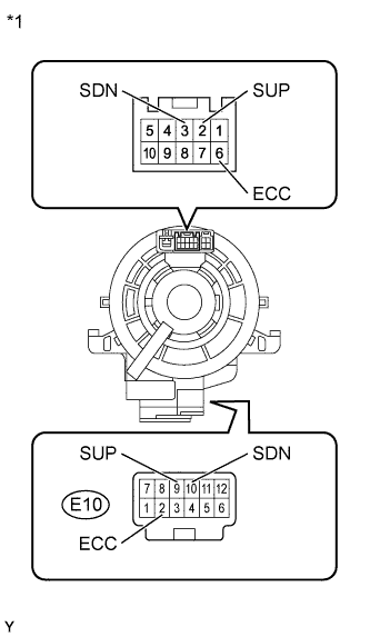
Text in Illustration*1
| Front view of wire harness connector
(to Spiral Cable Sub-assembly)
|
| | REPAIR OR REPLACE HARNESS OR CONNECTOR |
|
|
| 2.INSPECT SPIRAL CABLE SUB-ASSEMBLY |
Remove the spiral cable sub-assembly (RAV4_ACA30 RM000001DNS00EX.html).
Measure the resistance according to the value(s) in the table below.
- Standard Resistance:
Tester Connection
| Condition
| Specified Condition
|
2 (SUP) - E10-9 (SUP)
| Always
| Below 1 Ω
|
3 (SDN) - E10-10 (SDN)
| Always
| Below 1 Ω
|
6 (ECC) - E10-2 (ECC)
| Always
| Below 1 Ω
|
Text in Illustration*1
| Component without harness connected
(Spiral Cable Sub-assembly)
|
| 3.INSPECT TRANSMISSION SHIFT SWITCH ASSEMBLY (LH (-) AND RH (+)) |
Remove the transmission shift switch assembly (RAV4_ACA30 RM000003WO9001X.html).
Measure the resistance according to the value(s) in the table below.
- Standard Resistance:
for LHTester Connection
| Switch Condition
| Specified Condition
|
SDN - ECC
| "-" shift paddle operated and held (down-shift)
| Below 2.5 Ω
|
SDN - ECC
| "-" shift paddle not operated (down-shift)
| 1 MΩ or higher
|
for RHTester Connection
| Switch Condition
| Specified Condition
|
SUP - ECC
| "+" shift paddle operated and held (up-shift)
| Below 2.5 Ω
|
SUP - ECC
| "+" shift paddle not operated (up-shift)
| 1 MΩ or higher
|
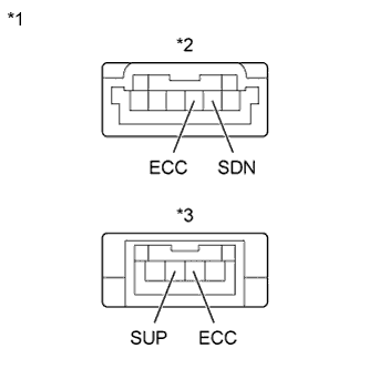
Text in Illustration*1
| Component without harness connected
(Transmission Shift Switch Assembly)
|
*2
| for LH
|
*3
| for RH
|
| 4.INSPECT NO. 1 SWITCH WIRE |
Disconnect the No. 1 switch wire connector.
Measure the resistance according to the value(s) in the table below.
- Standard Resistance:
Tester Connection
| Switch Condition
| Specified Condition
|
SDN - ECC
| "-" shift paddle operated and held (down-shift)
| Below 2.5 Ω
|
SUP - ECC
| "+" shift paddle operated and held (up-shift)
| Below 2.5 Ω
|
SDN - ECC
| "-" shift paddle not operated (down-shift)
| 1 MΩ or higher
|
SUP - ECC
| "+" shift paddle not operated (up-shift)
| 1 MΩ or higher
|
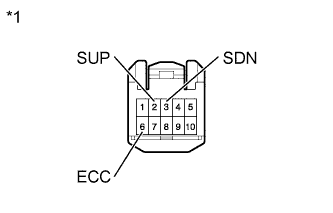
Text in Illustration*1
| Component without harness connected
(No. 1 Switch Wire)
|
| 5.INSPECT STEERING PAD SWITCH ASSEMBLY |
Disconnect the steering pad switch assembly connector.
Measure the resistance according to the value(s) in the table below.
- Standard Resistance:
Tester Connection
| Switch Condition
| Specified Condition
|
2 (SUP) - 6 (ECC)
| "+" shift paddle operated and held (up-shift)
| Below 2.5 Ω
|
3 (SDN) - 6 (ECC)
| "-" shift paddle operated and held (down-shift)
| Below 2.5 Ω
|
2 (SUP) - 6 (ECC)
| "+" shift paddle not operated (up-shift)
| 1 MΩ or higher
|
3 (SDN) - 6 (ECC)
| "-" shift paddle not operated (down-shift)
| 1 MΩ or higher
|
Text in Illustration*1
| Front view of wire harness connector
(to Spiral Cable Sub-assembly)
|
| 6.CHECK HARNESS AND CONNECTOR (SPIRAL CABLE - ECM) |
Disconnect the ECM connector.
Disconnect the transmission control switch (shift lock control unit assembly) connector.
Measure the resistance according to the value(s) in the table below.
- Standard Resistance:
Tester Connection
| Switch Condition
| Specified Condition
|
A12-16 (SFTU) - Body ground
| "+" shift paddle operated and held (up-shift)
| Below 2.5 Ω
|
A12-51 (SFTD) - Body ground
| "-" shift paddle operated and held (down-shift)
| Below 2.5 Ω
|
A12-16 (SFTU) - Body ground
| "+" shift paddle not operated (up-shift)
| 1 MΩ or higher
|
A12-51 (SFTD) - Body ground
| "-" shift paddle not operated (down-shift)
| 1 MΩ or higher
|
Text in Illustration*1
| Front view of wire harness connector
(to ECM)
|
| | REPAIR OR REPLACE HARNESS OR CONNECTOR |
|
|
Replace the ECM (RAV4_ACA30 RM0000017UO01KX.html).
- NOTICE:
- Performing reset memory will clear the learned values of both the yaw rate sensor assembly*1 or deceleration sensor*2 (deceleration sensor 0 point calibration) and CVT oil pressure (CVT oil pressure calibration). Make sure to perform reset memory, yaw rate sensor assembly*1 or deceleration sensor*2 0 point calibration and CVT oil pressure calibration when replacing any of the parts shown in the following table:
Replaced Part
|
- Continuously variable transaxle assembly
- ECM
- Oil pressure sensor
- Yaw rate sensor assembly (w/ VSC)
- Deceleration sensor (w/o VSC)
- Brake actuator assembly (skid control ECU)
|
- After performing reset memory, always perform yaw rate sensor assembly*1 or deceleration sensor*2 (deceleration sensor 0 point) calibration first, and then CVT oil pressure calibration.
- Always perform 0 point calibration with the vehicle on level ground.
- Do not shake or vibrate the vehicle during 0 point calibration.
Using the intelligent tester, perform reset memory, deceleration sensor 0 point calibration and CVT oil pressure calibration (RAV4_ACA30 RM000003UQR002X.html).
Check that no DTC is stored.