DTC P1550 Battery Current Sensor Circuit
DTC P1551 Battery Current Sensor Circuit Low
DTC P1552 Battery Current Sensor Circuit High
Description
The battery current sensor installed on the positive battery terminal detects the amount of current supplied from the alternator.
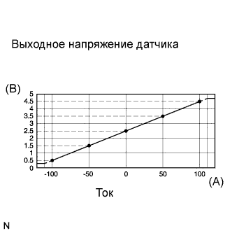
The battery current sensor changes current to voltage and outputs that voltage. The battery current sensor changes current at the positive battery terminal to voltage and sends it to the ECM. The ECM controls the voltage of the alternator based on the signals from the battery current sensor.
Toyota fault code list DTC P1550 DTC P1551 DTC P1552
| DTC No. | DTC Detection Condition | Trouble Area |
| P1550 | The following condition continues for 10 seconds or more with the ignition switch on (IG) (1 trip detection logic):
|
|
| P1551 | Battery current sensor output value is 0.2 V or less for 0.55 seconds or more with the ignition switch on (IG) (1 trip detection logic) |
|
| P1552 | Battery current sensor output value is 4.8 V or more for 0.55 seconds or more with the ignition switch on (IG) (1 trip detection logic) |
|
Wiring diagram
Inspection procedure
NOTICE:
After replacing the ECM, the new ECM needs registration and initialization.
HINT:
If DTCs relating to different systems are output, and they share terminal E2 as their ground, check this ground circuit first.
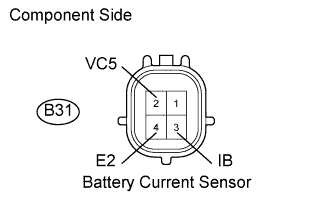
| 1.INSPECT BATTERY CURRENT SENSOR ASSEMBLY |
-
Disconnect the B31 battery current sensor connector.
-
Measure the resistance of the battery current sensor.
Standard resistance:
Tester Connection Specified Condition B31-2 (VC5) - B31-4 (E2) 3 to 10 k? B31-3 (IB)- B31-4 (E2) 3 to 10 k? B31-2 (VC5) - B31-3 (IB) Below 0.5 k? HINT:
The resistance differs according to the tester type.
-
Reconnect the battery current sensor connector.
|
|
||||
| OK | |
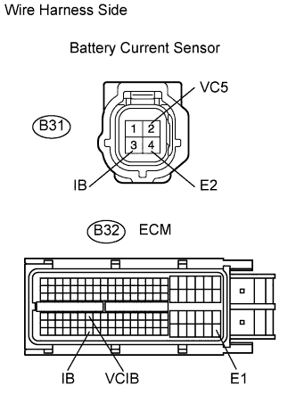
| 2.CHECK WIRE HARNESS (BATTERY CURRENT SENSOR - ECM) |
-
Disconnect the B31 battery current sensor connector.
-
Disconnect the B32 ECM connector.
-
Measure the resistance of the wire harness side connectors.
Standard resistance:
Tester Connection Specified Condition B31-2 (VC5) - B32-70 (VCIB) Below 1 ? B31-3 (IB)- B32-116 (IB) Below 1 ? B31-4 (E2) - E1 (B32-109) Below 1 ? B31-2 (VC5) or B32-70 (VCIB) - Body ground 10 k? or higher B31-3 (IB)or B32-116 (IB) - Body ground 10 k? or higher -
Reconnect the battery current sensor connector.
-
Reconnect the ECM connector.
|
|
||||
| OK | |
|