K111F Cvt. Toyota Rav4. Aca30, 33, 38 Gsa33 Zsa30, 35
DESCRIPTION
WIRING DIAGRAM
INSPECTION PROCEDURE
CHECK DTC OUTPUT (IN ADDITION TO DTC P1585)
READ VALUE USING INTELLIGENT TESTER (G SENSOR)
REPLACE BRAKE ACTUATOR ASSEMBLY (SKID CONTROL ECU)
PERFORM INITIALIZATION
REPLACE YAW RATE SENSOR ASSEMBLY
PERFORM INITIALIZATION
CHECK WHETHER DTC OUTPUT RECURS
REPLACE BRAKE ACTUATOR ASSEMBLY (SKID CONTROL ECU)
PERFORM INITIALIZATION
CHECK HARNESS AND CONNECTOR (DECELERATION SENSOR - BRAKE ACTUATOR ASSEMBLY)
INSPECT DECELERATION SENSOR (POWER SOURCE)
INSPECT DECELERATION SENSOR (GL1 VOLTAGE)
REPLACE BRAKE ACTUATOR ASSEMBLY (SKID CONTROL ECU)
PERFORM INITIALIZATION
REPLACE BRAKE ACTUATOR ASSEMBLY (SKID CONTROL ECU)
PERFORM INITIALIZATION
REPLACE DECELERATION SENSOR
PERFORM INITIALIZATION
DTC P1585 Acceleration Sensor Circuit |
DESCRIPTION
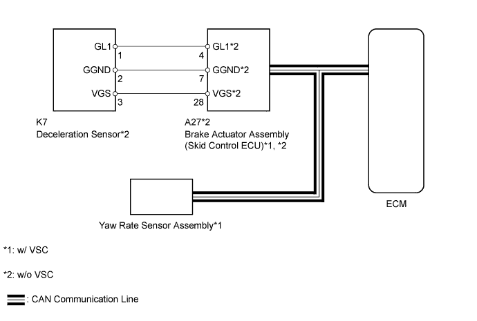
- *1: w/ VSC
- *2: w/o VSC
The ECM determines the vehicle inclination based on a signal from the yaw rate sensor assembly*1 or deceleration sensor*2.- HINT:
- If a CAN communication DTC is output, perform troubleshooting for that DTC first.
DTC Code
| DTC Detection Condition
- Diagnosis Condition
- Malfunction Status
- Malfunction Time
- Other
| Trouble Area
|
P1585
| - The ignition switch is ON.
- The output value of the yaw rate sensor assembly*1 or deceleration sensor*2 remains at -1.5 G or less, or 1.5 G or more for at least 1.2 seconds.
- 3.0 seconds
- 1 trip detection logic
| - Yaw rate sensor assembly (w/ VSC)
- Deceleration sensor (w/o VSC)
- Brake actuator assembly (Skid control ECU)
|
- The ignition switch is ON.
- The power source voltage to the yaw rate sensor assembly*1 or deceleration sensor*2 remains at 4.4 V or less, or 5.6 V or higher for at least 1.2 seconds.
- 3.0 seconds
- 1 trip detection logic
|
- The ignition switch is ON.
- No signal from the yaw rate sensor assembly*1 or deceleration sensor*2 is detected 7 times or more.
- 3.0 seconds
- 1 trip detection logic
|
- The ignition switch is ON.
- With the vehicle stopped, the difference between GL1 and GL2 does not become less than 0.4 G within 60 seconds after exceeding 0.6 G.
- 3.0 seconds
- 1 trip detection logic
|
- The ignition switch is ON.
- A yaw rate sensor assembly*1 or deceleration sensor*2 power source voltage malfunction signal is received for at least 10 seconds with the vehicle speed at 3 km/h (1.8 mph) or more.
- 3.0 seconds
- 1 trip detection logic
|
WIRING DIAGRAM
INSPECTION PROCEDURE
- *1: w/ VSC
- *2: w/o VSC
| 1.CHECK DTC OUTPUT (IN ADDITION TO DTC P1585) |
Connect the intelligent tester to the DLC3.
Turn the ignition switch to ON.
Turn the intelligent tester on.
Enter the following menus: Powertrain / Engine and ECT / DTC.
Read the DTCs using the tester.
ResultResult
| Proceed to
|
Only P1585 is output
| A
|
P1585 and other DTCs are output
| B
|
- HINT:
- If any other DTCs besides DTC P1585 are output, perform troubleshooting for those DTCs first.
| 2.READ VALUE USING INTELLIGENT TESTER (G SENSOR) |
Connect the intelligent tester to the DLC3.
Turn the ignition switch to ON.
Turn the intelligent tester on.
Enter the following menus: Powertrain / Engine and ECT / Data List.
In accordance with the display on the tester, read the Data List.
Engine and ECTTester Display
| Measurement Item/Range
| Normal Condition
| Diagnostic Note
|
G sensor
| Converted output voltage of yaw rate sensor assembly*1 or deceleration sensor*2/
min.: 0 V
max.: 5 V
| Displays converted voltage of yaw rate sensor assembly*1 or deceleration sensor*2
- Vehicle on level ground: 2.31 V to 2.69 V
- Decelerating: 1.88 V to 2.5 V
- Accelerating: 2.5 V to 3.11 V
- G sensor malfunction: Set to 1.87 V
- Communication malfunction: Set to 1.87 V
| -
|
ResultResult
| Proceed to
|
Data displayed is as specified under Normal Condition
| A
|
Data displayed is not as specified under Normal Condition (w/ VSC)
| B
|
Data displayed is not as specified under Normal Condition (w/o VSC)
| C
|
| 3.REPLACE BRAKE ACTUATOR ASSEMBLY (SKID CONTROL ECU) |
Replace the brake actuator assembly (skid control ECU).
- w/ VSC (RAV4_ACA30 RM000001XV200PX.html).
- w/o VSC (RAV4_ACA30 RM000001XV200OX.html).
- NOTICE:
- Performing reset memory will clear the learned values of both the yaw rate sensor assembly*1 or deceleration sensor*2 (deceleration sensor 0 point calibration) and CVT oil pressure (CVT oil pressure calibration). Make sure to perform reset memory, yaw rate sensor assembly*1 or deceleration sensor*2 0 point calibration and CVT oil pressure calibration when replacing any of the parts shown in the following table:
Replaced Part
|
- Continuously variable transaxle assembly
- ECM
- Oil pressure sensor
- Yaw rate sensor assembly (w/ VSC)
- Deceleration sensor (w/o VSC)
- Brake actuator assembly (skid control ECU)
|
- After performing reset memory, always perform yaw rate sensor assembly*1 or deceleration sensor*2 (deceleration sensor 0 point) calibration first, and then CVT oil pressure calibration.
- Always perform 0 point calibration with the vehicle on level ground.
- Do not shake or vibrate the vehicle during 0 point calibration.
Using the intelligent tester, perform reset memory, deceleration sensor 0 point calibration and CVT oil pressure calibration (RAV4_ACA30 RM000003UQR002X.html).
Check that no DTC is stored.
| 5.REPLACE YAW RATE SENSOR ASSEMBLY |
Replace the yaw rate sensor assembly (RAV4_ACA30 RM000001XVQ009X.html).
- NOTICE:
- Performing reset memory will clear the learned values of both the yaw rate sensor assembly*1 or deceleration sensor*2 (deceleration sensor 0 point calibration) and CVT oil pressure (CVT oil pressure calibration). Make sure to perform reset memory, yaw rate sensor assembly*1 or deceleration sensor*2 0 point calibration and CVT oil pressure calibration when replacing any of the parts shown in the following table:
Replaced Part
|
- Continuously variable transaxle assembly
- ECM
- Oil pressure sensor
- Yaw rate sensor assembly (w/ VSC)
- Deceleration sensor (w/o VSC)
- Brake actuator assembly (skid control ECU)
|
- After performing reset memory, always perform yaw rate sensor assembly*1 or deceleration sensor*2 (deceleration sensor 0 point) calibration first, and then CVT oil pressure calibration.
- Always perform 0 point calibration with the vehicle on level ground.
- Do not shake or vibrate the vehicle during 0 point calibration.
Using the intelligent tester, perform reset memory, deceleration sensor 0 point calibration and CVT oil pressure calibration (RAV4_ACA30 RM000003UQR002X.html).
| 7.CHECK WHETHER DTC OUTPUT RECURS |
Clear the DTCs (RAV4_ACA30 RM000000W770KGX.html).
Check whether DTC P1585 is output.
ResultResult
| Proceed to
|
P1585 is output
| A
|
No DTC output
| B
|
| 8.REPLACE BRAKE ACTUATOR ASSEMBLY (SKID CONTROL ECU) |
Replace the brake actuator assembly (skid control ECU) (RAV4_ACA30 RM000001XV200PX.html).
- NOTICE:
- Performing reset memory will clear the learned values of both the yaw rate sensor assembly*1 or deceleration sensor*2 (deceleration sensor 0 point calibration) and CVT oil pressure (CVT oil pressure calibration). Make sure to perform reset memory, yaw rate sensor assembly*1 or deceleration sensor*2 0 point calibration and CVT oil pressure calibration when replacing any of the parts shown in the following table:
Replaced Part
|
- Continuously variable transaxle assembly
- ECM
- Oil pressure sensor
- Yaw rate sensor assembly (w/ VSC)
- Deceleration sensor (w/o VSC)
- Brake actuator assembly (skid control ECU)
|
- After performing reset memory, always perform yaw rate sensor assembly*1 or deceleration sensor*2 (deceleration sensor 0 point) calibration first, and then CVT oil pressure calibration.
- Always perform 0 point calibration with the vehicle on level ground.
- Do not shake or vibrate the vehicle during 0 point calibration.
Using the intelligent tester, perform reset memory, deceleration sensor 0 point calibration and CVT oil pressure calibration (RAV4_ACA30 RM000003UQR002X.html).
Check that no DTC is stored.
| 10.CHECK HARNESS AND CONNECTOR (DECELERATION SENSOR - BRAKE ACTUATOR ASSEMBLY) |
Disconnect the deceleration sensor connector.
Disconnect the brake actuator assembly (skid control ECU) connector.
Measure the resistance according to the value(s) in the table below.
- Standard Resistance:
Tester Connection
| Condition
| Specified Condition
|
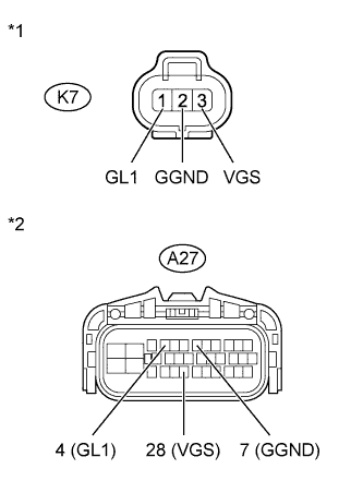
K7-1 (GL1) - A27-4 (GL1)
| Always
| Below 1 Ω
|
K7-2 (GGND) - A27-7 (GGND)
| Always
| Below 1 Ω
|
K7-3 (VGS) - A27-28 (VGS)
| Always
| Below 1 Ω
|
K7-1 (GL1) or A27-4 (GL1) - Body ground
| Always
| 10 kΩ or higher
|
K7-2 (GGND) or A27-7 (GGND) - Body ground
| Always
| 10 kΩ or higher
|
K7-3 (VGS) or A27-28 (VGS) - Body ground
| Always
| 10 kΩ or higher
|
Text in Illustration*1
| Front view of wire harness connector
(to Deceleration Sensor)
|
*2
| Front view of wire harness connector
(to Brake Actuator Assembly (Skid Control ECU))
|
| | REPAIR OR REPLACE HARNESS OR CONNECTOR |
|
|
| 11.INSPECT DECELERATION SENSOR (POWER SOURCE) |
Disconnect the deceleration sensor connector.
Turn the ignition switch to ON.
Measure the voltage according to the value(s) in the table below.
- Standard Voltage:
Tester Connection
| Switch Condition
| Specified Condition
|
K7-3 (VGS) - Body ground
| Ignition switch ON
| 4.5 to 5.5 V
|
Text in Illustration*1
| Front view of wire harness connector
(to Deceleration Sensor)
|
| 12.INSPECT DECELERATION SENSOR (GL1 VOLTAGE) |
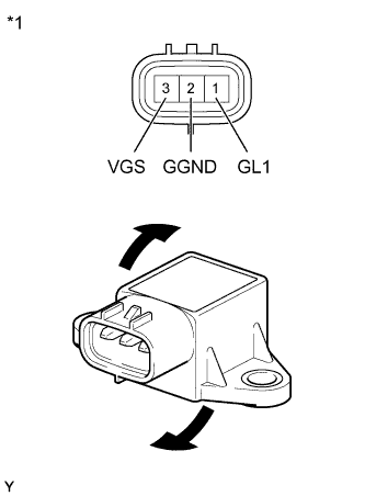
Remove the deceleration sensor (RAV4_ACA30 RM000001XVQ009X.html).
Connect 3 dry cell batteries of 1.5 V in series.
Connect the positive (+) lead of the batteries to terminal 3 (VGS) and the negative (-) lead to terminal 2 (GGND) to apply a voltage of 4.5 V.
- NOTICE:
- Do not apply 6 V or higher to terminals 3 (VGS) and 2 (GGND).
- If the sensor is dropped, replace it with a new one.
Measure the voltage according to the value(s) in the table below.
- Standard Voltage:
Tester Connection
| Condition
| Specified Condition
|
1 (GL1) - 2 (GGND)
| - 4.5 V applied to terminals 3 (VGS) and 2 (GGND)
- Sensor not tilted
| Approx. 2.5 V
|
1 (GL1) - 2 (GGND)
| - 4.5 V applied to terminals 3 (VGS) and 2 (GGND)
- Sensor tilted back and forth
| Changes between approx. 0.5 V and 4.5 V
|
- HINT:
- If the sensor is tilted too much, it may output the wrong value.
Text in Illustration*1
| Component without harness connected
(Deceleration Sensor)
|
| 13.REPLACE BRAKE ACTUATOR ASSEMBLY (SKID CONTROL ECU) |
Replace the brake actuator assembly (skid control ECU) (RAV4_ACA30 RM000001XV200OX.html).
| 14.PERFORM INITIALIZATION |
- NOTICE:
- Performing reset memory will clear the learned values of both the yaw rate sensor assembly*1 or deceleration sensor*2 (deceleration sensor 0 point calibration) and CVT oil pressure (CVT oil pressure calibration). Make sure to perform reset memory, yaw rate sensor assembly*1 or deceleration sensor*2 0 point calibration and CVT oil pressure calibration when replacing any of the parts shown in the following table:
Replaced Part
|
- Continuously variable transaxle assembly
- ECM
- Oil pressure sensor
- Yaw rate sensor assembly (w/ VSC)
- Deceleration sensor (w/o VSC)
- Brake actuator assembly (skid control ECU)
|
- After performing reset memory, always perform yaw rate sensor assembly*1 or deceleration sensor*2 (deceleration sensor 0 point) calibration first, and then CVT oil pressure calibration.
- Always perform 0 point calibration with the vehicle on level ground.
- Do not shake or vibrate the vehicle during 0 point calibration.
Using the intelligent tester, perform reset memory, deceleration sensor 0 point calibration and CVT oil pressure calibration (RAV4_ACA30 RM000003UQR002X.html).
Check that no DTC is stored.
| 15.REPLACE BRAKE ACTUATOR ASSEMBLY (SKID CONTROL ECU) |
Replace the brake actuator assembly (skid control ECU) (RAV4_ACA30 RM000001XV200OX.html).
| 16.PERFORM INITIALIZATION |
- NOTICE:
- Performing reset memory will clear the learned values of both the yaw rate sensor assembly*1 or deceleration sensor*2 (deceleration sensor 0 point calibration) and CVT oil pressure (CVT oil pressure calibration). Make sure to perform reset memory, yaw rate sensor assembly*1 or deceleration sensor*2 0 point calibration and CVT oil pressure calibration when replacing any of the parts shown in the following table:
Replaced Part
|
- Continuously variable transaxle assembly
- ECM
- Oil pressure sensor
- Yaw rate sensor assembly (w/ VSC)
- Deceleration sensor (w/o VSC)
- Brake actuator assembly (skid control ECU)
|
- After performing reset memory, always perform yaw rate sensor assembly*1 or deceleration sensor*2 (deceleration sensor 0 point) calibration first, and then CVT oil pressure calibration.
- Always perform 0 point calibration with the vehicle on level ground.
- Do not shake or vibrate the vehicle during 0 point calibration.
Using the intelligent tester, perform reset memory, deceleration sensor 0 point calibration and CVT oil pressure calibration (RAV4_ACA30 RM000003UQR002X.html).
Check that no DTC is stored.
| 17.REPLACE DECELERATION SENSOR |
Replace the deceleration sensor (RAV4_ACA30 RM000001XVQ009X.html).
| 18.PERFORM INITIALIZATION |
- NOTICE:
- Performing reset memory will clear the learned values of both the yaw rate sensor assembly*1 or deceleration sensor*2 (deceleration sensor 0 point calibration) and CVT oil pressure (CVT oil pressure calibration). Make sure to perform reset memory, yaw rate sensor assembly*1 or deceleration sensor*2 0 point calibration and CVT oil pressure calibration when replacing any of the parts shown in the following table:
Replaced Part
|
- Continuously variable transaxle assembly
- ECM
- Oil pressure sensor
- Yaw rate sensor assembly (w/ VSC)
- Deceleration sensor (w/o VSC)
- Brake actuator assembly (skid control ECU)
|
- After performing reset memory, always perform yaw rate sensor assembly*1 or deceleration sensor*2 (deceleration sensor 0 point) calibration first, and then CVT oil pressure calibration.
- Always perform 0 point calibration with the vehicle on level ground.
- Do not shake or vibrate the vehicle during 0 point calibration.
Using the intelligent tester, perform reset memory, deceleration sensor 0 point calibration and CVT oil pressure calibration (RAV4_ACA30 RM000003UQR002X.html).
Check that no DTC is stored.