Узел Топливного Бака - Узлы И Детали
Land Cruiser Prado GRJ150 TRJ150 TRJ155 KDJ150 TRJ155 LJ150 - ТОПЛИВНАЯ СИСТЕМА ДВИГАТЕЛЯ 5L-E
УЗЕЛ ТОПЛИВНОГО БАКА - УЗЛЫ И ДЕТАЛИ

1 / 1
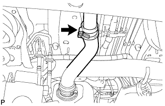
| 1. INSTALL FUEL TANK TO FILLER PIPE HOSE |
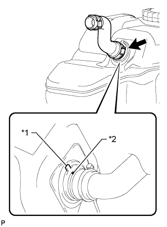
Align the fuel tank side mark with the hose side mark.
| *1 | Fuel Tank Side Mark |
| *2 | Hose Side Mark |
Install the fuel tank to filler pipe hose to the fuel tank.
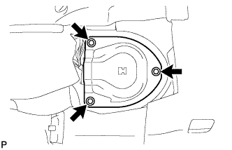
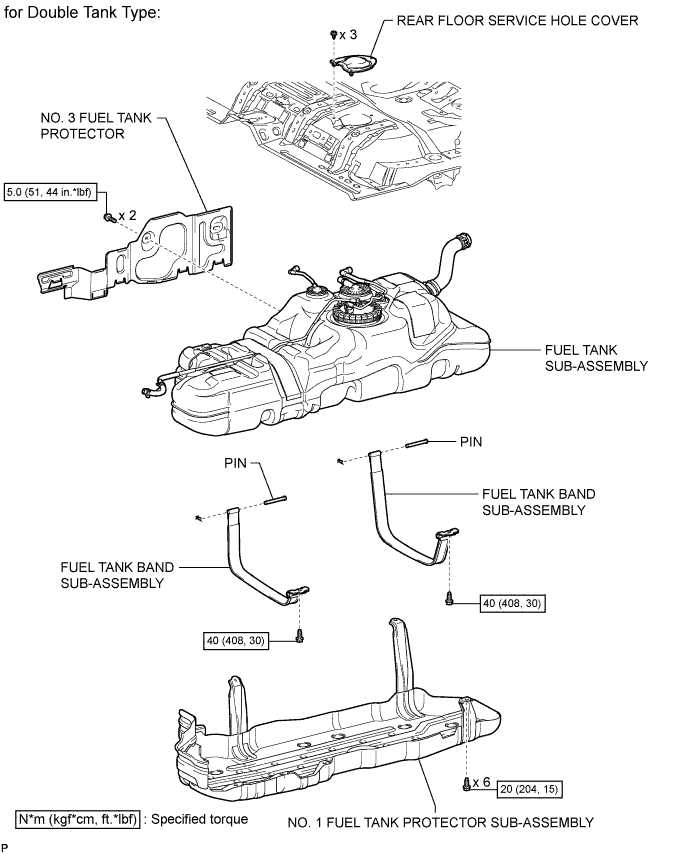
| 2. INSTALL NO. 3 FUEL TANK PROTECTOR |
Install the No. 3 fuel tank protector and attach the 4 clamps.
Install the 2 bolts.
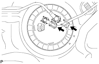
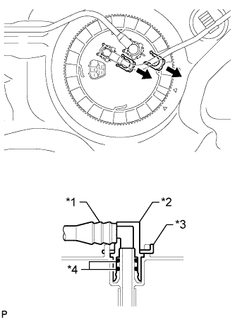
| 3. INSTALL FUEL TANK VENT TUBE ASSEMBLY |
Apply a light coat of gasoline or grease to a new gasket and install the gasket to the fuel tank.

Align the protrusion of the fuel tank vent tube with the groove of the fuel tank.
| *1 | Protrusion |
| *2 | Groove |
Install the fuel tank vent tube to the fuel tank.
Put a new retainer on the fuel tank. While holding the fuel tank vent tube, tighten the retainer one complete turn by hand.
| *1 | Start Mark (Fuel Tank Side) |
| *2 | Start Mark (Retainer Side) |


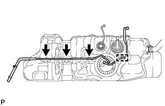
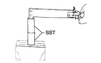
Set SST on the retainer.

Using SST, tighten the retainer until the mark on the retainer is within range A on the fuel tank as shown in the illustration.
| *1 | Fuel Tank Side Mark |
| *2 | Retainer Side Mark |
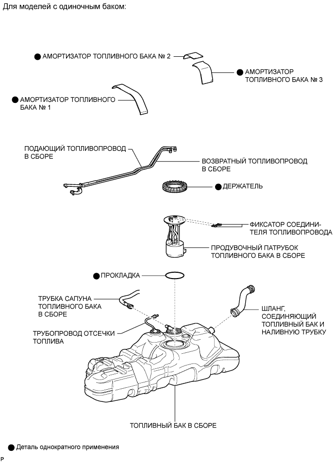
| 4. INSTALL FUEL TANK MAIN TUBE SUB-ASSEMBLY AND FUEL RETURN TUBE SUB-ASSEMBLY (for Single Tank Type) |

Install the fuel tank main tube and fuel return tube with the 2 fuel tube joint clips.

| *1 | Fuel Tube Joint |
| *2 | O-Ring |
| *3 | Fuel Tube |
| *4 | Fuel Tube Joint Clip |
| *a | CORRECT |
| *b | INCORRECT |
Install the fuel tank main tube and fuel return tube to the fuel tank.
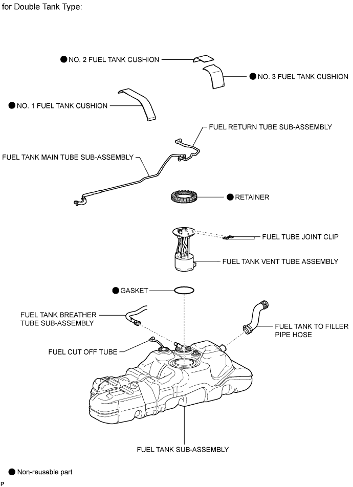
| 5. INSTALL FUEL TANK MAIN TUBE SUB-ASSEMBLY AND FUEL RETURN TUBE SUB-ASSEMBLY (for Double Tank Type) |
Install the fuel tank main tube and fuel return tube with the 2 fuel tube joint clips.
| *1 | Fuel Tube Joint |
| *2 | O-Ring |
| *3 | Fuel Tube |
| *4 | Fuel Tube Joint Clip |
| *a | CORRECT |
| *b | INCORRECT |
Install the fuel tank main tube to the fuel tank.
Install the fuel return tube to the fuel tank and attach the clamp.
| 6. INSTALL FUEL TANK CUSHION |
Install 3 new fuel tank cushions to the fuel tank.
| 7. INSTALL FUEL TANK SUB-ASSEMBLY |
Set the fuel tank on a transmission jack and rise the transmission jack.
Install the 2 fuel tank bands with the 2 pins and 2 clips.
Connect the 2 fuel tank bands with the 2 bolts.
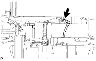
| 8. CONNECT FUEL TANK TO FILLER PIPE HOSE |
Connect the fuel tank to filler pipe hose to the filler pipe.
| 9. CONNECT FUEL TANK BREATHER TUBE SUB-ASSEMBLY (for Single Tank Type) |
Connect the fuel tank breather tube (See page ).
| 10. CONNECT FUEL CUT OFF TUBE (for Single Tank Type) |
| 11. CONNECT FUEL TANK BREATHER TUBE SUB-ASSEMBLY (for Double Tank Type) |
Connect the fuel tank breather tube (See page ).
| 12. CONNECT FUEL RETURN TUBE SUB-ASSEMBLY (for Double Tank Type) |
Connect the fuel return tube (See page ).
| 13. CONNECT FUEL CUT OFF TUBE (for Double Tank Type) |
Connect the fuel cut off tube (See page ).
| 14. CONNECT FUEL RETURN TUBE SUB-ASSEMBLY (for Single Tank Type) |
| 15. CONNECT FUEL TANK MAIN TUBE SUB-ASSEMBLY (for Single Tank Type) |
| 16. CONNECT FUEL TANK MAIN TUBE SUB-ASSEMBLY (for Double Tank Type) |
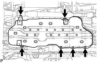
| 17. INSTALL NO. 1 FUEL TANK PROTECTOR SUB-ASSEMBLY |
Install the No. 1 fuel tank protector with the 6 bolts.
| 18. INSTALL REAR FLOOR SERVICE HOLE COVER |
Connect the fuel sender gauge connector.
Install the rear floor service hole cover with the 3 screws.
| 19. INSTALL REAR SEAT ASSEMBLY LH |
for 60/40 Split Double-folding Seat Type LH Side:
Install the rear seat assembly LH (See page ).
for 60/40 Split Slide Walk-in Seat Type LH Side:
Install the rear seat assembly LH (See page ).
| 20. CONNECT CABLE TO NEGATIVE BATTERY TERMINAL |
| 21. BLEED AIR FROM FUEL SYSTEM |

Using the hand pump mounted on the fuel filter cap, bleed the air from the fuel system. Continue pumping until the pump resistance increases.
| 22. INSPECT FOR FUEL LEAK |
Check that there are no fuel leaks anywhere in the fuel system after performing maintenance.
| 1. DISCONNECT CABLE FROM NEGATIVE BATTERY TERMINAL |
| 2. REMOVE REAR SEAT ASSEMBLY LH |
for 60/40 Split Double-folding Seat Type LH Side:
Remove the rear seat assembly LH (See page ).
for 60/40 Split Slide Walk-in Seat Type LH Side:
Remove the rear seat assembly LH (See page ).
| 3. REMOVE REAR FLOOR SERVICE HOLE COVER |
Remove the 3 screws and rear floor service hole cover.

Disconnect the fuel sender gauge connector.
| *A | for Single Tank Type |
| *B | for Double Tank Type |
| 4. REMOVE NO. 1 FUEL TANK PROTECTOR SUB-ASSEMBLY |
Remove the 6 bolts and No. 1 fuel tank protector.
| 5. DISCONNECT FUEL TANK MAIN TUBE SUB-ASSEMBLY (for Single Tank Type) |
| 6. DISCONNECT FUEL RETURN TUBE SUB-ASSEMBLY (for Single Tank Type) |

| 7. DISCONNECT FUEL TANK MAIN TUBE SUB-ASSEMBLY (for Double Tank Type) |
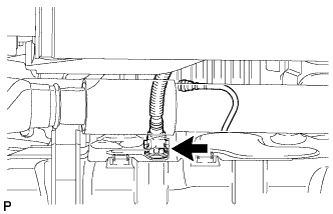
| 8. DISCONNECT FUEL CUT OFF TUBE (for Single Tank Type) |
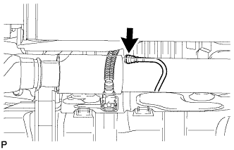
| 9. DISCONNECT FUEL TANK BREATHER TUBE SUB-ASSEMBLY (for Single Tank Type) |
Disconnect the fuel tank breather tube (See page ).
| 10. DISCONNECT FUEL CUT OFF TUBE (for Double Tank Type) |
Disconnect the fuel cut off tube (See page ).
| 11. DISCONNECT FUEL RETURN TUBE SUB-ASSEMBLY (for Double Tank Type) |

Disconnect the fuel return tube (See page ).
| 12. DISCONNECT FUEL TANK BREATHER TUBE SUB-ASSEMBLY (for Double Tank Type) |

Disconnect the fuel tank breather tube (See page ).
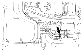
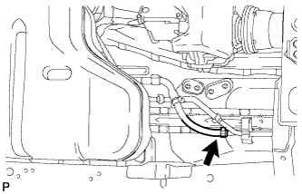
| 13. DISCONNECT FUEL TANK TO FILLER PIPE HOSE |
Disconnect the fuel tank to filler pipe hose from the filler pipe.
| 14. REMOVE FUEL TANK SUB-ASSEMBLY |
Place a transmission jack under the fuel tank.

Remove the 2 bolts, 2 clips, 2 pins and 2 fuel tank bands.
Slowly lower the transmission jack slightly.
| 15. REMOVE FUEL TANK CUSHION |

Remove the No. 1, No. 2 and No. 3 fuel tank cushions from the fuel tank.
| *1 | No. 1 Fuel Tank Cushion |
| *2 | No. 2 Fuel Tank Cushion |
| *3 | No. 3 Fuel Tank Cushion |
| 16. REMOVE FUEL TANK MAIN TUBE SUB-ASSEMBLY AND FUEL RETURN TUBE SUB-ASSEMBLY (for Single Tank Type) |

Remove the 2 fuel tube joint clips and pull out the fuel tank main tube and fuel return tube.
| *1 | Fuel Tube |
| *2 | Fuel Tube Joint |
| *3 | Fuel Tube Joint Clip |
| *4 | O-Ring |

Remove the fuel tank main tube and fuel return tube from the fuel tank.
| 17. REMOVE FUEL TANK MAIN TUBE SUB-ASSEMBLY AND FUEL RETURN TUBE SUB-ASSEMBLY (for Double Tank Type) |
Remove the 2 fuel tube joint clips and pull out the fuel tank main tube and fuel return tube.
| *1 | Fuel Tube |
| *2 | Fuel Tube Joint |
| *3 | Fuel Tube Joint Clip |
| *4 | O-Ring |
Detach the clamp and remove the fuel return tube.
Remove the fuel tank main tube from the fuel tank.
| 18. REMOVE FUEL TANK VENT TUBE ASSEMBLY |
Set SST on the retainer.

Using SST, loosen the retainer.
 | Turn |
Remove the retainer.
Remove the fuel tank vent tube assembly from the fuel tank.
Remove the gasket from the fuel tank.
| 19. REMOVE NO. 3 FUEL TANK PROTECTOR |

Remove the 2 bolts.
Detach the 4 clamps and remove the No. 3 fuel tank protector.
| 20. REMOVE FUEL TANK TO FILLER PIPE HOSE |

Remove the fuel tank to filler pipe hose from the fuel tank.

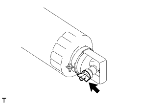
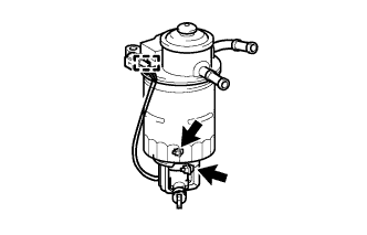
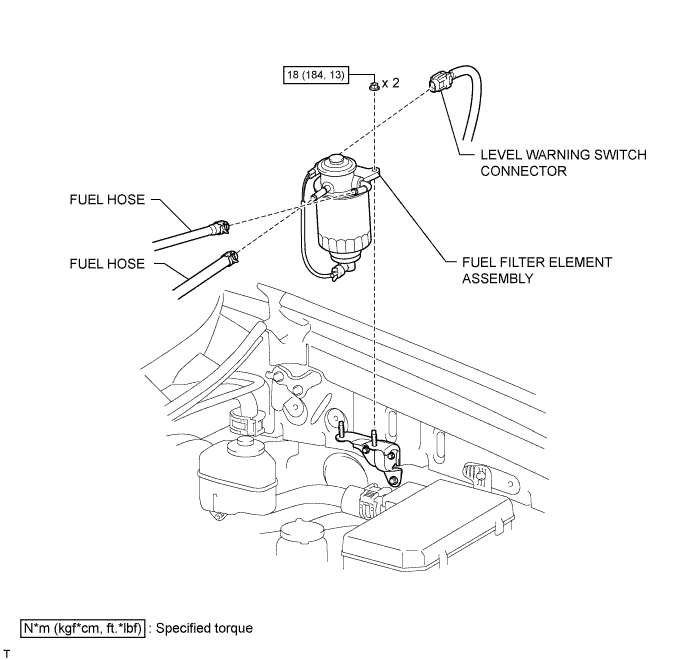
| 1. REMOVE FUEL FILTER ASSEMBLY |

Disconnect the 2 fuel hoses.
Disconnect the level warning switch connector.
Remove the 2 nuts and fuel filter.
| 2. DRAIN FUEL |
Loosen the fuel filter drain plug and drain the fuel from the fuel filter.
| 3. REMOVE FUEL FILTER CASE |
Detach the level warning switch connector clamp from the fuel filter cap.
Remove the 2 bolts, fuel filter case and fuel filter gasket.
| 4. REMOVE LEVEL WARNING SWITCH |

Clamp the fuel filter cap in a vise between aluminum plates.
Using pliers, remove the level warning switch.
Remove the warning switch gasket from the level warning switch.
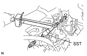
| 5. REMOVE FUEL FILTER ELEMENT ASSEMBLY |
Using SST, remove the fuel filter element.
| 6. INSTALL FUEL FILTER ELEMENT ASSEMBLY |
Check and clean the installation surface of the fuel filter element.
Apply fuel to the gasket of a new fuel filter element.
Lightly screw the fuel filter element into place, and tighten it until the gasket comes into contact with the seat.

Tighten the fuel filter element an additional 3/4 turn by hand.
| 7. INSTALL LEVEL WARNING SWITCH |
Install a new level warning switch gasket to the level warning switch.
Apply fuel to the level warning switch gasket of the level warning switch.

Install the level warning switch to the fuel filter element and tighten it by hand.
| *a | Front |
| *b | Within 28.4° |
| 8. INSTALL FUEL FILTER CASE |
Install the fuel filter gasket and fuel filter case to the fuel filter element.

Tighten the 2 bolts.
Attach the level warning switch connector clamp to the fuel filter cap.
| *a | Front |
| *b | 0 to 20° |
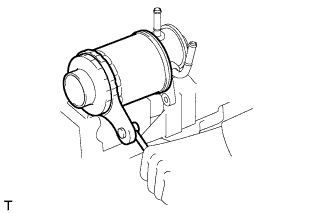
| 9. INSTALL FUEL FILTER ASSEMBLY |
Install the fuel filter with the 2 nuts.

Connect the level warning switch connector.
Connect the 2 fuel hoses.
| *a | Upper |
| 10. BLEED AIR FROM FUEL SYSTEM |
Using the hand pump mounted on the fuel filter cap, bleed the air from the fuel system. Continue pumping until the pump resistance increases.
| 11. INSPECT FOR FUEL LEAK |
Check that there are no fuel leaks anywhere in the fuel system after performing maintenance.

| 1. INSTALL NOZZLE HOLDER AND NOZZLE SET |
Install 4 new injection nozzle seat gaskets and the 4 injection nozzle seats to the injection nozzle holes of the cylinder head.
Using SST, install the 4 nozzle holder and nozzle sets.
| 2. INSTALL NOZZLE LEAKAGE PIPE ASSEMBLY |
Install 4 new ring packing washers and the leakage pipe with the 4 nuts.
Connect the fuel hose to the leakage pipe.
| 3. INSTALL NO. 1 GLOW PLUG CONNECTOR |
Install the No. 1 glow plug resistor insulator and No. 1 glow plug connector.

Install the glow plug connector with the 4 nuts. Uniformly tighten the nuts.
| *1 | Nut |
| *2 | Washer |
| *3 | No. 2 Glow Plug Resistor Insulator |
| *4 | Engine Wire |
| *5 | No. 1 Glow Plug Connector |
| *6 | No. 1 Glow Plug Resistor Insulator |
| *7 | Bolt |
Install the 4 screw grommets.
Connect the engine wire and install the No. 2 glow plug resistor insulator and washer with the bolt.
| 4. INSTALL INJECTION PIPE SET |
Install the 2 lower clamps to the intake manifold.

Install the 4 injection pipes.
| *a | for Injection Nozzle Side |
| *b | for Injection Pump Side |
Install the 2 upper pipe clamps with the 2 nuts.
| 5. INSTALL DIESEL THROTTLE BODY |
Install the diesel throttle body (See page ).
| 6. CONNECT CABLE TO NEGATIVE BATTERY TERMINAL |
| 7. BLEED INJECTION PIPE |
Move the hand pump on the upper part of the fuel filter up and down and fill the injection pump and fuel system with fuel.
Loosen one of the union nuts (on the nozzle side).
Crank the engine until fuel comes out from the union nut connection (on the nozzle side).
Tighten the union nut.
Perform the procedures above for each injection pipe.
| 8. INSPECT FOR FUEL LEAK |
Check that there are no fuel leaks anywhere in the fuel system after performing maintenance.
| 1. INSTALL NOZZLE RETAINING NUT |
Install the pressure pin, distance piece and nozzle assembly to the nozzle retaining nut.
Install the nozzle holder pressure spring and adjusting shim, and then temporarily install the nozzle holder to the nozzle retaining nut.
Using SST, tighten the nozzle retaining nut.
Inspect the holder and nozzle set.
| 2. INSTALL RING PACKING SETTING NUT |
Install a new washer and the ring packing setting nut.
| 1. INSPECT NOZZLE HOLDER AND NOZZLE SET |
Pressure test:

Install the nozzle holder to an injection nozzle hand tester and bleed air from the union nut connection.

Pump the tester handle a few times as fast as possible to discharge the carbon from the injection hole.
Pump the tester handle slowly and observe the pressure gauge.
Read the pressure gauge just as the injection pressure begins to drop.
| Specified Condition | ||
| 0.900 mm (0.0354 in.) | 1.300 mm (0.0512 in.) | 1.700 mm (0.0669 in.) |
| 0.950 mm (0.0374 in.) | 1.350 mm (0.0531 in.) | 1.750 mm (0.0709 in.) |
| 1.000 mm (0.0394 in.) | 1.400 mm (0.0551 in.) | 1.800 mm (0.0728 in.) |
| 1.050 mm (0.0413 in.) | 1.450 mm (0.0571 in.) | 1.850 mm (0.0728 in.) |
| 1.100 mm (0.0433 in.) | 1.500 mm (0.0591 in.) | 1.900 mm (0.0748 in.) |
| 1.150 mm (0.0453 in.) | 1.550 mm (0.0610 in.) | 1.950 mm (0.0768 in.) |
| 1.200 mm (0.0472 in.) | 1.600 mm (0.0630 in.) | - |
| 1.250 mm (0.0492 in.) | 1.650 mm (0.0650 in.) | - |

Leakage test:
While maintaining pressure at approximately 981 to 1961 kPa (10.0 to 20.0 kgf/cm2, 142 to 284 psi) below the injection pressure (adjust using the tester handle), check that there is no dripping from the injection hole or around the retaining nut for 10 seconds.
| *a | No Good |
| *b | Good |
If the nozzle drips within 10 seconds, replace or clean and overhaul the nozzle assembly.

Spray pattern test:
The injection nozzle should shudder at a certain pumping speed between 30 and 60 times per minute.
Check the spray pattern during shuddering.
| *a | No Good |
| *b | Good |
If the spray pattern is not correct during shuddering, replace or clean the nozzle.
| 2. CLEAN NOZZLE ASSEMBLY |

Using a wooden stick and brass brush, clean the nozzle.
Using a wooden stick, remove the carbon adhering to the nozzle needle tip.
| *1 | Wooden Stick |

Using a brass brush, remove the carbon from the exterior of the nozzle body (except lapped surface).
| 3. INSPECT NOZZLE ASSEMBLY |
Wash the nozzle in clean diesel fuel.

Perform the following test several times, rotating the needle slightly each time.
Tilt the nozzle body approximately 60° and pull the needle out approximately one third of its length.
Check that the needle falls into the body vent smoothly by its own weight when released.
If the needle does not fall smoothly, replace the nozzle assembly.
| 1. REMOVE RING PACKING SETTING NUT |
Remove the ring packing setting nut and washer.
| 2. REMOVE NOZZLE RETAINING NUT |

Using SST, remove the nozzle retaining nut.
| 3. REMOVE NOZZLE HOLDER PRESSURE SPRING |
| 4. REMOVE ADJUSTING SHIM |
| 5. REMOVE NOZZLE HOLDER PRESSURE PIN |
| 6. REMOVE NOZZLE DISTANCE PIECE |
| 7. REMOVE NOZZLE ASSEMBLY |