Dtc 42 Vehicle Speed Sensor Signal Circuit Malfunction
Land Cruiser Prado GRJ150 TRJ150 TRJ155 KDJ150 TRJ155 LJ150 - СИСТЕМА УПРАВЛЕНИЯ ДВИГАТЕЛЕМ 5L-E
DESCRIPTION
WIRING DIAGRAM
INSPECTION PROCEDURE
CHECK SPEEDOMETER (OPERATION)
CHECK ECM (SP1 VOLTAGE)
CHECK HARNESS AND CONNECTOR (COMBINATION METER ASSEMBLY - ECM)
DTC 42 Vehicle Speed Sensor Signal Circuit Malfunction
DESCRIPTION
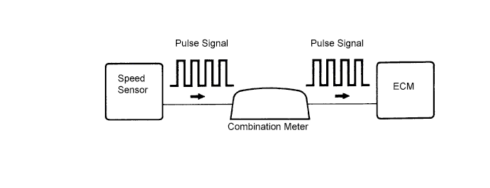
The vehicle speed sensor outputs a pulse signal according to the revolution of the rotor shaft, which is rotated by the transmission output shaft via the driven gear. After this signal is converted into a more precise rectangular waveform by the waveform shaping circuit inside the combination meter, it is then transmitted to the ECM. The ECM determines the vehicle speed based on the frequency of this pulse signal.
| DTC No. | DTC Detection Condition | Trouble Area |
| 42 | All conditions below are detected continuously for 8 sec. or more: Vehicle speed signal: 0 km/h (0 mph). Engine speed: 2000 to 3300 rpm. Engine coolant temperature: 70°C (158°F) or higher. Accelerator pedal opening amount: 60% or more. | Open or short in vehicle speed sensor circuit Vehicle speed sensor Combination meter ECM |
WIRING DIAGRAM
INSPECTION PROCEDURE
| 1.CHECK SPEEDOMETER (OPERATION) |
Drive the vehicle and check if the operation of the speedometer in the combination meter assembly is normal.
- OK:
- The speedometer operates normally according to vehicle speed.
- УКАЗАНИЕ:
- The vehicle speed sensor is operating normally if the speedometer display is normal.
|
| ||||
| OK | |
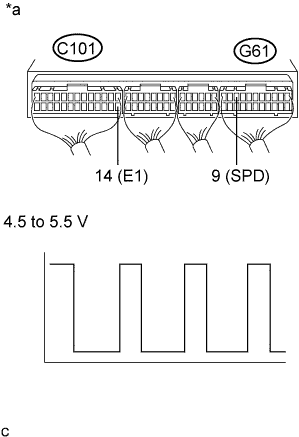
| 2.CHECK ECM (SP1 VOLTAGE) |
Move the shift lever to N.
Jack up the vehicle.
Turn the ignition switch to ON.
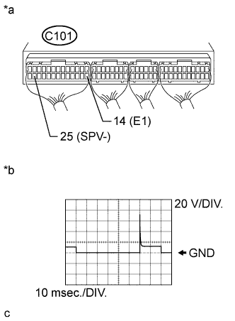
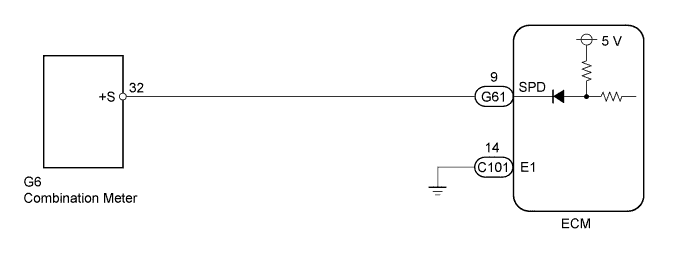
Check the waveform between the specified terminals of the ECM connectors as the rear wheels are turned slowly.
- OK:
Tester Connection Switch Condition Specified Condition G61-9 (SPD) - C101-14 (E1) Ignition switch ON Correct waveform is as shown
| *a | Component with harness connected (ECM) |
|
| ||||
| OK | ||
| ||
| 3.CHECK HARNESS AND CONNECTOR (COMBINATION METER ASSEMBLY - ECM) |
Disconnect the ECM connector.
Disconnect the combination meter assembly connector.
Measure the resistance according to the value(s) in the table below.
- Standard Resistance (Check for Open):
Tester Connection Condition Specified Condition G61-9 (SPD) - G6-32 Always Below 1 Ω
- Standard Resistance (Check for Short):
Tester Connection Condition Specified Condition G61-9 (SPD) or G6-32 - Body ground Always 10 kΩ or higher
Reconnect the ECM connector.
Reconnect the combination meter assembly connector.
|
| ||||
| OK | ||
| ||