DTC 19 (1) Accelerator Position Sensor Circuit Malfunction
DESCRIPTION
This is a troubleshooting procedure for the accelerator pedal position sensor.
This electrical throttle system does not use a throttle cable.
This accelerator pedal position sensor is a non-contact type.
The accelerator pedal position sensor is mounted on the accelerator pedal to detect the position of the accelerator pedal. Since this sensor is electronically controlled with hall elements, accurate control and reliability can be obtained. It has 2 sensors in order to detect the accelerator position and malfunctions of the accelerator position sensor.
Due to the accelerator pedal position sensor, the voltage applied to terminals VPA and VPA2 of the ECM changes between 0 V and 5 V according to the position of the accelerator pedal. VPA is a signal which indicates the actual accelerator pedal position and is used for engine control, and VPA2 is a signal which indicates information about the position and is used for detecting malfunctions. Based on the signals input to terminals VPA and VPA2, the ECM determines the current position of the accelerator pedal and controls the injection pump.

| DTC No. | DTC Detection Condition | Trouble Area |
| 19 (1) | Condition (a), (b), (c) or (d) continues for 2.0 seconds:
(a) VPA is 0.2 V or less and VPA2 is 0.5 V or less.
(b) VPA is 4.8 V or higher.
(c) VPA is 0.2 V or higher and 3.45 V or less, and VPA2 is 4.8 V or higher.
(d) "VPA minus VPA2" is 0.02 V or less. | Open or short in accelerator pedal position sensor circuit
Accelerator pedal position sensor
ECM
|
Condition (a) continues for 0.5 seconds:
(a) VPA is 0.2 V or less, or VPA2 is 0.5 V or less. |
- After confirming DTC 19 (1), use the intelligent tester to confirm the throttle valve opening amount.
| Trouble Area | Accelerator Pedal Position Expressed as Voltage |
| Accelerator pedal released | Accelerator pedal depressed |
| ACCEL POS #1 | ACCEL POS #2 | ACCEL POS #1 | ACCEL POS #2 |
| VC circuit open | 0 to 0.2 V | 0 to 0.2 V | 0 to 0.2 V | 0 to 0.2 V |
| VPA circuit open or shorted to ground | 0 to 0.2 V | 1.2 to 2.0 V | 0 to 0.2 V | 3.4 to 5.3 V |
| VPA2 circuit open or shorted to ground | 0.5 to 1.1 V | 0 to 0.2 V | 2.6 to 4.5 V | 0 to 0.2 V |
| E2 circuit open | 4.5 to 5.5 V | 4.5 to 5.5 V | 4.5 to 5.5 V | 4.5 to 5.5 V |
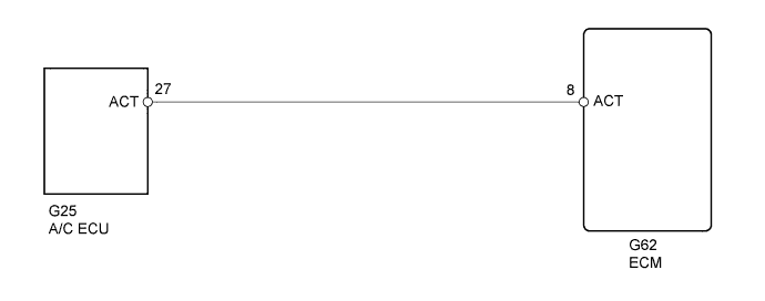
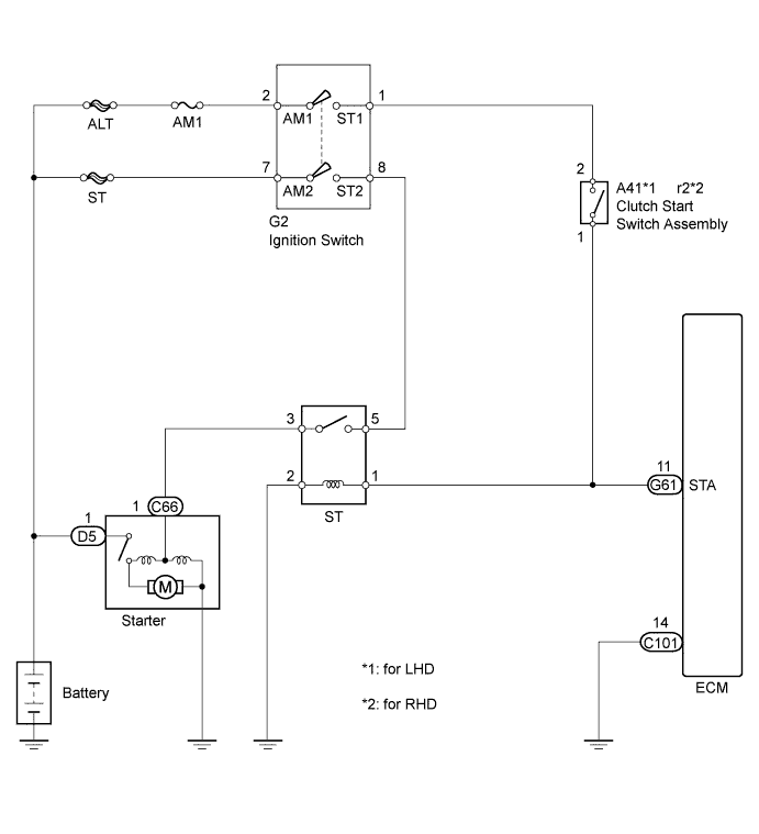
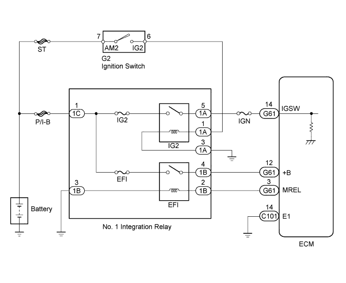
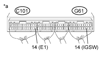
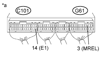
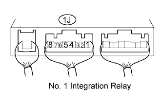
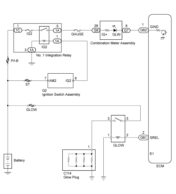
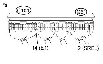
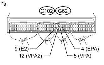
WIRING DIAGRAM

INSPECTION PROCEDURE
- Read freeze frame data using the intelligent tester. Freeze frame data records the engine condition when malfunctions are detected. When troubleshooting, freeze frame data can help determine if the vehicle was moving or stationary, if the engine was warmed up or not, and other data from the time the malfunction occurred.
When using intelligent tester:
| 1.READ VALUE USING INTELLIGENT TESTER (ACCELERATOR POSITION) |
Connect the intelligent tester to the DLC3.
Turn the ignition switch to ON.
Enter the following menus: Powertrain / Engine and ECT / Data List / Accel Position.
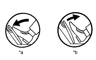
Check that the value displayed on the intelligent tester changes when repeatedly depressing and releasing the accelerator pedal.
Text in Illustration| *a | Depressed |
| *b | Released |
| 2.READ OUTPUT DTC (CHECK IF ACCELERATOR PEDAL POSITION SENSOR DTC IS OUTPUT AGAIN) |
Connect the intelligent tester to the DLC3.
Clear the DTC (See page ).
Turn the ignition switch off for 30 seconds or more.
Start the engine and idle it for 15 seconds or more.
Read the DTCs (See page ).
Result| Result | Proceed to |
| DTC 19 (1) output again | A |
| No DTC output | B |
| 3.CHECK HARNESS AND CONNECTOR (ECM - ACCELERATOR PEDAL POSITION SENSOR) |
Disconnect the accelerator pedal position sensor connector.
Disconnect the ECM connector.
Measure the resistance according to the value(s) in the table below.
- Standard Resistance (Check for Open):
| Tester Connection | Condition | Specified Condition |
| A19-1 (VCP2) - C102-1 (VC) | Always | Below 1 Ω |
| A19-2 (EPA2) - C102-9 (E2) | Always | Below 1 Ω |
| A19-3 (VPA2) - G62-12 (VPA2) | Always | Below 1 Ω |
| A19-4 (VCPA) - G62-6 (VCPA) | Always | Below 1 Ω |
| A19-5 (EPA) - G62-4 (EPA) | Always | Below 1 Ω |
| A19-6 (VPA) - G62-5 (VPA) | Always | Below 1 Ω |
- Standard Resistance (Check for Short):
| Tester Connection | Condition | Specified Condition |
| A19-1 (VCP2) or C102-1 (VC) - Body ground | Always | 10 kΩ or higher |
| A19-2 (EPA2) or C102-9 (E2) - Body ground | Always | 10 kΩ or higher |
| A19-3 (VPA2) or G62-12 (VPA2) - Body ground | Always | 10 kΩ or higher |
| A19-4 (VCPA) or G62-6 (VCPA) - Body ground | Always | 10 kΩ or higher |
| A19-5 (EPA) or G62-4 (EPA) - Body ground | Always | 10 kΩ or higher |
| A19-6 (VPA) or G62-5 (VPA) - Body ground | Always | 10 kΩ or higher |
Reconnect the accelerator pedal position sensor connector.
Reconnect the ECM connector.
| | REPAIR OR REPLACE HARNESS OR CONNECTOR |
|
|
| 4.CHECK ECM (VC, VCPA VOLTAGE) |
Disconnect the accelerator pedal position sensor connector.
Turn the ignition switch to ON.
Measure the voltage according to the value(s) in the table below.
- Standard Voltage:
| Tester Connection | Switch Condition | Specified Condition |
| C102-1 (VC) - C102-9 (E2) | Ignition switch ON | 4.5 to 5.5 V |
| G62-6 (VCPA) - G62-4 (EPA) | Ignition switch ON | 4.5 to 5.5 V |
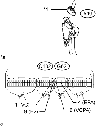
Text in Illustration| *1 | Accelerator pedal position sensor connector |
| *a | Component with harness connected
(ECM) |
Reconnect the accelerator pedal position sensor connector.
| 5.REPLACE ACCELERATOR PEDAL ROD ASSEMBLY |
Replace the accelerator pedal rod assembly (See page ).
| 6.READ OUTPUT DTC (CHECK IF ACCELERATOR PEDAL POSITION SENSOR DTC IS OUTPUT AGAIN) |
Connect the intelligent tester to the DLC3.
Clear the DTC (See page ).
Turn the ignition switch off for 30 seconds or more.
Start the engine and idle it for 15 seconds or more.
Read the DTCs (See page ).
Result| Result | Proceed to |
| DTC 19 (1) output again | A |
| No DTC output | B |
When not using intelligent tester:
| 1.CHECK HARNESS AND CONNECTOR (ECM - ACCELERATOR PEDAL POSITION SENSOR) |
Disconnect the accelerator pedal position sensor connector.
Disconnect the ECM connector.
Measure the resistance according to the value(s) in the table below.
- Standard Resistance (Check for Open):
| Tester Connection | Condition | Specified Condition |
| A19-1 (VCP2) - C102-1 (VC) | Always | Below 1 Ω |
| A19-2 (EPA2) - C102-9 (E2) | Always | Below 1 Ω |
| A19-3 (VPA2) - G62-12 (VPA2) | Always | Below 1 Ω |
| A19-4 (VCPA) - G62-6 (VCPA) | Always | Below 1 Ω |
| A19-5 (EPA) - G62-4 (EPA) | Always | Below 1 Ω |
| A19-6 (VPA) - G62-5 (VPA) | Always | Below 1 Ω |
- Standard Resistance (Check for Short):
| Tester Connection | Condition | Specified Condition |
| A19-1 (VCP2) or C102-1 (VC) - Body ground | Always | 10 kΩ or higher |
| A19-2 (EPA2) or C102-9 (E2) - Body ground | Always | 10 kΩ or higher |
| A19-3 (VPA2) or G62-12 (VPA2) - Body ground | Always | 10 kΩ or higher |
| A19-4 (VCPA) or G62-6 (VCPA) - Body ground | Always | 10 kΩ or higher |
| A19-5 (EPA) or G62-4 (EPA) - Body ground | Always | 10 kΩ or higher |
| A19-6 (VPA) or G62-5 (VPA) - Body ground | Always | 10 kΩ or higher |
Reconnect the accelerator pedal position sensor connector.
Reconnect the ECM connector.
| | REPAIR OR REPLACE HARNESS OR CONNECTOR |
|
|
| 2.CHECK ECM (VC, VCPA VOLTAGE) |
Disconnect the accelerator pedal position sensor connector.
Turn the ignition switch to ON.
Measure the voltage according to the value(s) in the table below.
- Standard Voltage:
| Tester Connection | Switch Condition | Specified Condition |
| C102-1 (VC) - C102-9 (E2) | Ignition switch ON | 4.5 to 5.5 V |
| G62-6 (VCPA) - G62-4 (EPA) | Ignition switch ON | 4.5 to 5.5 V |
Text in Illustration| *1 | Accelerator pedal position sensor connector |
| *a | Component with harness connected
(ECM) |
Reconnect the accelerator pedal position sensor connector.
| 3.REPLACE ACCELERATOR PEDAL ROD ASSEMBLY |
Replace the accelerator pedal rod assembly (See page ).
| 4.READ OUTPUT DTC (CHECK IF ACCELERATOR PEDAL POSITION SENSOR DTC IS OUTPUT AGAIN) |
Connect the intelligent tester to the DLC3.
Clear the DTC (See page ).
Turn the ignition switch off for 30 seconds or more.
Start the engine and idle it for 15 seconds or more.
Read the DTCs (See page ).
Result| Result | Proceed to |
| DTC 19 (1) output again | A |
| No DTC output | B |