Педаль Акселератора - Узлы И Детали
Land Cruiser Prado GRJ150 TRJ150 TRJ155 KDJ150 TRJ155 LJ150 - СИСТЕМА УПРАВЛЕНИЯ ДВИГАТЕЛЕМ 5L-E
ПЕДАЛЬ АКСЕЛЕРАТОРА - УЗЛЫ И ДЕТАЛИ

1 / 1
| 1. INSTALL NO. 2 ECM BRACKET |
Install the No. 2 ECM bracket with the 2 screws.
| 2. INSTALL NO. 1 ECM BRACKET |
Install the No. 1 ECM bracket with the 2 screws.
| 3. INSTALL WIRE HARNESS CLAMP BRACKET (for LHD) |
Install the wire harness clamp bracket with the 2 screws.
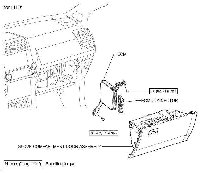
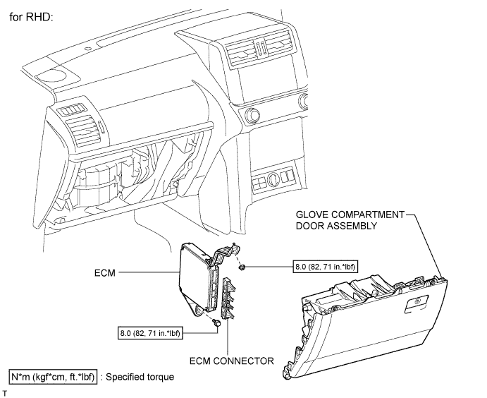
| 4. INSTALL ECM |
Install the ECM with the bolt and nut.
Connect the 4 connectors.
| 5. INSTALL GLOVE COMPARTMENT DOOR ASSEMBLY |
Install the glove compartment door (See page ).
| 1. REMOVE GLOVE COMPARTMENT DOOR ASSEMBLY |
Remove the glove compartment door (See page ).
| 2. REMOVE ECM |

Disconnect the 4 connectors.
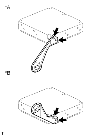
| *A | for LHD |
| *B | for RHD |
Remove the bolt, nut and ECM.
| 3. REMOVE WIRE HARNESS CLAMP BRACKET (for LHD) |

Remove the 2 screws and wire harness clamp bracket.
| 4. REMOVE NO. 1 ECM BRACKET |

Remove the 2 screws and No. 1 ECM bracket.
| 5. REMOVE NO. 2 ECM BRACKET |
Remove the 2 screws and No. 2 ECM bracket.
| *A | for LHD |
| *B | for RHD |

| 1. INSTALL DIESEL THROTTLE BODY |
Place a new gasket and the diesel throttle body on the intake manifold.
Connect the throttle control motor connector.
Connect the throttle open switch connector.
| 2. INSTALL INTAKE FLANGE |
Install a new gasket and the intake flange with the 3 nuts.
Connect the PCV hose.
Connect the manifold absolute pressure sensor connector.
Connect the heater water hose with the bolt.
| 3. INSTALL INTAKE PIPE |
Install the intake pipe with the 2 bolts and tighten the hose clamp.
| 4. INSTALL RESONATOR WITH AIR CLEANER CAP SUB-ASSEMBLY |
Вставьте петли крышки воздушного фильтра и шланг в корпус воздушного фильтра, а затем закрепите 4 откидных защелки.
Установите крышку воздушного фильтра и закрепите ее зажимом.
Закрепите зажим жгута проводов.
Подсоедините 2 зажима и разъем.
| 1. INSPECT DIESEL THROTTLE BODY |
Inspect the throttle control motor.

Measure the resistance according to the value(s) in the table below.
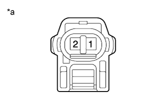
| Tester Connection | Condition | Specified Condition |
| 1 - 2 | 20°C (68°F) | 18 to 22 Ω |
| 2 - 3 | 20°C (68°F) | 18 to 22 Ω |
| 4 - 5 | 20°C (68°F) | 18 to 22 Ω |
| 5 - 6 | 20°C (68°F) | 18 to 22 Ω |
| *a | Component without harness connected (Diesel Throttle Body) |
If the result is not as specified, replace the diesel throttle body.
Inspect the throttle open switch.
Measure the resistance according to the value(s) in the table below.
| Tester Connection | Condition | Specified Condition |
| 1 - 2 | Fully open | Below 1 Ω |
| 1 - 2 | Fully close | 10 kΩ or higher |
| *a | Component without harness connected (Diesel Throttle Body) |
If the result is not as specified, replace the diesel throttle body.
| 1. REMOVE RESONATOR WITH AIR CLEANER CAP SUB-ASSEMBLY |

Disconnect the sensor connector.
Detach the wire harness clamp.
Loosen the hose clamp and remove the resonator with air cleaner cap.

Detach the 4 hook clamps, and then remove the air cleaner cap and resonator with air cleaner cap.
| 2. REMOVE INTAKE PIPE |

Remove the 2 bolts.
Loosen the hose clamp and remove the intake pipe.
| 3. REMOVE INTAKE FLANGE |

Remove the bolt and disconnect the heater water hose.
| *A | w/o Rear Heater |
| *B | w/ Rear Heater |
Disconnect the manifold absolute pressure sensor connector.

Disconnect the PCV hose.
Remove the 3 nuts, intake flange and gasket.
| 4. REMOVE DIESEL THROTTLE BODY |

Disconnect the throttle open switch connector.
Disconnect the throttle control motor connector.
Remove the diesel throttle body and gasket.

Terminals TC and CG are located in the DLC3.
The DLC3 is located under the instrument panel under cover. When terminals TC and CG are connected, DTCs in normal mode or test mode can be read from the Malfunction Indicator Lamp (MIL) in the combination meter assembly.
Also, terminal SIL is located in the DLC3. This terminal is used for M-OBD communication with the intelligent tester.

| 1.CHECK DLC3 (CHECK VOLTAGE) |

Measure the voltage according to the value(s) in the table below.
| Tester Connection | Condition | Specified Condition |
| G48-16 (BAT) - G48-4 (CG) | Always | 11 to 14 V |
| *a | Front view of wire harness connector (to DLC3) |
|
| ||||
| OK | |
| 2.CHECK HARNESS AND CONNECTOR (ECM - DLC3) |
Disconnect the ECM connector.
Measure the resistance according to the value(s) in the table below.
| Tester Connection | Condition | Specified Condition |
| G61-15 (SIL) - G48-7 (SIL) | Always | Below 1 Ω |
| G61-4 (TC) - G48-13 (TC) | Always | Below 1 Ω |
| Tester Connection | Condition | Specified Condition |
| G61-15 (SIL) or G48-7 (SIL) - Body ground | Always | 10 kΩ or higher |
| G61-4 (TC) or G48-13 (TC) - Body ground | Always | 10 kΩ or higher |
Reconnect the ECM connector.
|
| ||||
| OK | ||
| ||
| 3.CHECK DLC3 |

Measure the resistance according to the value(s) in the table below.
| Tester Connection | Condition | Specified Condition |
| G48-4 (CG) - Body ground | Always | Below 1 Ω |
| *a | Front view of wire harness connector (to DLC3) |
|
| ||||
| OK | ||
| ||
The MIL is used to inform the user when the ECM has detected a vehicle malfunction.
By turning the ignition switch to ON, power is supplied to the MIL circuit and the ECM provides the circuit ground that illuminates the MIL.
Operation of the MIL should be checked visually: When the ignition switch is first turned to ON, the MIL should illuminate. When the engine is started, the MIL should turn off.

| 1.CHECK MIL CONDITION |
Check the MIL condition.
| Condition | Proceed to |
| MIL remains on | A |
| MIL does not illuminate | B |
|
| ||||
| A | |
| 2.CHECK IF MIL TURNS OFF |
Connect the intelligent tester to the DLC3.
Turn the ignition switch to ON and turn the tester on.
Check if DTCs have been stored (See page ). If DTCs are stored, write them down.
Clear the DTCs using the intelligent tester (See page ).
Check that the MIL turns off.
|
| ||||
| OK | ||
| ||
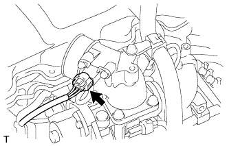
| 3.CHECK HARNESS AND CONNECTOR (FOR SHORT) |
Disconnect the ECM connector.
Turn the ignition switch to ON.
Check that the MIL is not illuminated.
| *a | Rear view of wire harness connector (to ECM) |
Reconnect the ECM connector.
|
| ||||
| OK | ||
| ||
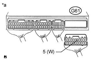
| 4.CHECK HARNESS AND CONNECTOR (ECM - COMBINATION METER ASSEMBLY) |
Disconnect the ECM connector.
Disconnect the combination meter assembly connector.
Measure the resistance according to the value(s) in the table below.
| Tester Connection | Condition | Specified Condition |
| G61-5 (W) - G7-7 (CHK) | Always | Below 1 Ω |
| Tester Connection | Condition | Specified Condition |
| G61-5 (W) or G7-7 (CHK) - Body ground | Always | 10 kΩ or higher |
Reconnect the ECM connector.
Reconnect the combination meter assembly connector.
|
| ||||
| OK | ||
| ||
| 5.CHECK IF MIL ILLUMINATES |
Check that the MIL illuminates when turning the ignition switch to ON.
|
| ||||
| OK | ||
| ||
| 6.INSPECT COMBINATION METER ASSEMBLY (MIL CIRCUIT) |
Refer to the combination meter assembly troubleshooting procedures (See page ).
|
| ||||
| OK | ||
| ||