Lighting System Light Control Switch Circuit

Body Electrical. Lexus Gs430, Gs300. Uzs190 Grs190
Lighting. Lexus Gs430, Gs300. Uzs190 Grs190

DESCRIPTION

WIRING DIAGRAM

INSPECTION PROCEDURE

READ VALUE OF INTELLIGENT TESTER

INSPECT FUSE (ECU-IG RH, MPX-B, D/C CUT)

CHECK WIRE HARNESS (BATTERY - COMBINATION SWITCH - BODY GROUND)

LIGHTING SYSTEM - Light Control Switch Circuit


DESCRIPTION

The combination switch receives the information of the light control switch, and sends it to each ECU via the multiplex communication system.

WIRING DIAGRAM


Lexus Gs430, Gs300. Uzs190 Grs190.Lighting.Lighting System.Lighting System  Light Control Switch Circuit


INSPECTION PROCEDURE

1.READ VALUE OF INTELLIGENT TESTER
  1. Check the Data List for proper functioning of the engine room No. 2 relay block.

    Engine room No. 2 relay block:

    Item
    Measurement Item / Display (Range)
    Normal Condition
    Diagnostic Note
    F Fog Light SW
    Front fog light switch signal ON or OFF
    ON: Front fog light switch is in ON position
    OFF: Front fog light switch is not in ON position
    -
    R Fog Light SW
    Rear fog light switch signal ON or OFF
    ON: Rear fog light switch is in ON position
    OFF: Rear fog light switch is not in ON position

    Dimmer Hi SW
    High beam switch signal / ON or OFF
    ON: Headlight dimmer switch is in HI position
    OFF: Headlight dimmer switch is not in HI position
    -
    Light Auto SW
    Auto light switch signal / ON or OFF
    ON: Light control switch is in AUTO position
    OFF: Light control switch is not in AUTO position
    -
    Head Light SW
    Headlight control switch signal / ON or OFF
    ON: Light control switch is in HEAD position
    OFF: Light control switch is not in HEAD position
    -
    Tail Light SW
    Taillight switch signal / ON or OFF
    ON: Light control switch is in TAIL or HEAD position
    OFF: Light control switch is not in TAIL or HEAD position
    -
    Turn Left SW
    Turn signal switch LH signal / ON or OFF
    ON: Light control switch is in LH position
    OFF: Light control switch is not in LH position
    -
    Turn Right SW
    Turn signal switch RH signal / ON or OFF
    ON: Light control switch is in RH position
    OFF: Light control switch is not in RH position
    -
    Telesc Short SW
    Telesco Short switch status / ON or OFF
    ON: Telesco switch is in SHORT position
    OFF: Telesco switch is not in SHORT position
    -
    Telesc Long SW
    Telesco Long switch status / ON or OFF
    ON: Telesco switch is in LONG position
    OFF: Telesco switch is not in LONG position
    -
    Tilt Down SW
    Tilt Down switch / ON or OFF
    ON: TILT switch is in DOWN position
    OFF: TILT switch is not in DOWN position
    -
    Tilt up SW
    Tilt Up switch / ON or OFF
    ON: TILT switch is in UP position
    OFF: TILT switch is not in UP position
    -
    IG SW Sig
    Engine switch signal / ON or OFF
    ON: Engine switch on (IG)
    OFF: Engine switch off
    -


NG
Go to step 2
OK

PROCEED TO NEXT CIRCUIT INSPECTION SHOWN IN PROBLEM SYMPTOMS TABLE

2.INSPECT FUSE (ECU-IG RH, MPX-B, D/C CUT)
  1. Remove the ECU-IG RH fuse from the cowl side junction block RH .

  1. Remove the MPX-B fuse from the engine room No. 1 relay block.

  1. Remove the D/C CUT fuse from the engine room No. 1 relay block.

  1. Measure the resistance of the fuses.

    Standard resistance:
    Below 1 Ω


NG
REPLACE FUSE
OK


3.CHECK WIRE HARNESS (BATTERY - COMBINATION SWITCH - BODY GROUND)


    Lexus Gs430, Gs300. Uzs190 Grs190.Lighting.Lighting System.Lighting System  Light Control Switch Circuit
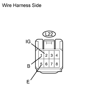
  1. Disconnect the L22 switch connector.

  1. Measure the voltage and resistance of the wire harness side connector.

    Standard voltage:
    Tester Connection
    Condition
    Specified Condition
    L22-2 (IG) - L22-5 (E)
    Engine switch on (IG)
    10 to 14 V
    L22-1 (B) - L22-5 (E)
    Always
    10 to 14 V
    Standard resistance:
    Tester Connection
    Specified Condition
    L22-5 (E) - Body ground
    Below 1 Ω


NG
REPAIR OR REPLACE HARNESS AND CONNECTOR
OK

PROCEED TO NEXT CIRCUIT INSPECTION SHOWN IN PROBLEM SYMPTOMS TABLE