Rear Seat Entertainment System Display Signal Circuit Between Radio Receiver And Television Display Assembly
DESCRIPTION
WIRING DIAGRAM
INSPECTION PROCEDURE
CHECK HARNESS AND CONNECTOR (MULTI-MEDIA MODULE RECEIVER ASSEMBLY - TELEVISION DISPLAY ASSEMBLY)
REAR SEAT ENTERTAINMENT SYSTEM - Display Signal Circuit between Radio Receiver and Television Display Assembly |
DESCRIPTION
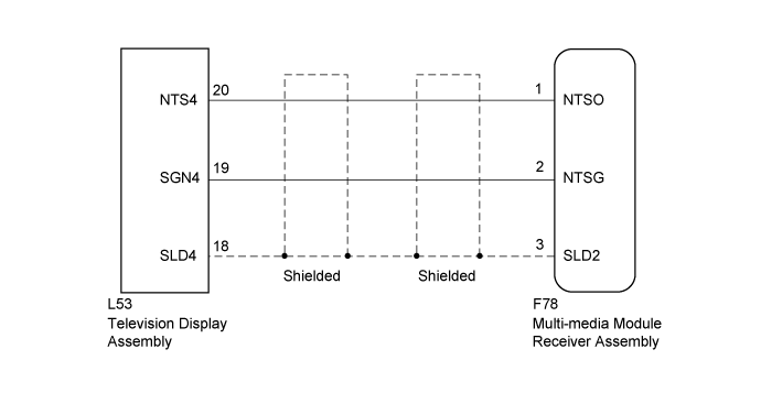
This is the display signal circuit from the multi-media module receiver assembly to the television display assembly.
WIRING DIAGRAM
INSPECTION PROCEDURE
| 1.CHECK HARNESS AND CONNECTOR (MULTI-MEDIA MODULE RECEIVER ASSEMBLY - TELEVISION DISPLAY ASSEMBLY) |
Disconnect the F78 multi-media module receiver assembly connector.
Disconnect the L53 television display assembly connector.
Measure the resistance according to the value(s) in the table below.
- Standard Resistance:
Tester Connection
| Condition
| Specified Condition
|
F78-1 (NTSO) - L53-20 (NTS4)
| Always
| Below 1 Ω
|
F78-2 (NTSG) - L53-19 (SGN4)
| Always
| Below 1 Ω
|
F78-3 (SLD2) - L53-18 (SLD4)
| Always
| Below 1 Ω
|
F78-1 (NTSO) - Body ground
| Always
| 10 kΩ or higher
|
F78-2 (NTSG) - Body ground
| Always
| 10 kΩ or higher
|
F78-3 (SLD2) - Body ground
| Always
| 10 kΩ or higher
|
| | REPAIR OR REPLACE HARNESS OR CONNECTOR |
|
|
| OK |
|
|
|
| PROCEED TO NEXT SUSPECTED AREA SHOWN IN PROBLEM SYMPTOMS TABLE (Click here) |
|