Cruise Control System Clutch Switch Circuit
DESCRIPTION
WIRING DIAGRAM
INSPECTION PROCEDURE
INSPECT CLUTCH SWITCH ASSEMBLY
CHECK HARNESS AND CONNECTOR (CLUTCH SWITCH ASSEMBLY -
BATTERY)
CHECK HARNESS AND CONNECTOR (ECM - CLUTCH SWITCH ASSEMBLY)
CRUISE CONTROL SYSTEM - Clutch Switch Circuit |
DESCRIPTION
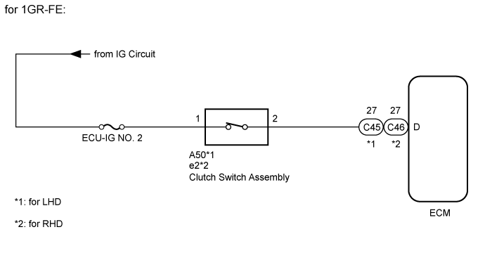
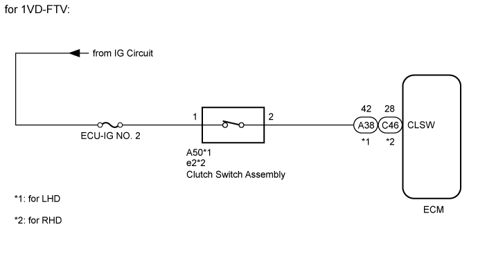
When the clutch pedal is released, the ECM receives positive (+) battery voltage through the LH-IG fuse. While depressing the clutch pedal, the clutch switch sends a signal to terminal D*1 or CLSW*2 of the ECM. The ECM cancels cruise control when terminal D*1 or CLSW*2 receives the signal.- HINT:
- *1: for 1GR-FE
- *2: for 1VD-FTV
WIRING DIAGRAM
INSPECTION PROCEDURE
- NOTICE:
- Inspect the fuses for circuits related to this system before performing the following inspection procedure.
| 1.INSPECT CLUTCH SWITCH ASSEMBLY |
Remove the clutch switch assembly.
- for LHD: Click here
- for RHD: Click here
Inspect the clutch switch assembly.
- for LHD: Click here
- for RHD: Click here
ResultResult
| Proceed to
|
OK
| A
|
NG (for LHD)
| B
|
NG (for RHD)
| C
|
| 2.CHECK HARNESS AND CONNECTOR (CLUTCH SWITCH ASSEMBLY -
BATTERY) |
Disconnect the A50*1 or e2*2 clutch switch assembly connector.
- *1: for LHD
- *2: for RHD
Measure the voltage according to the value(s) in the table below.
- Standard Voltage:
Tester Connection
| Switch Condition
| Specified Condition
|
A50*1-1 - Body ground
e2*2-1 - Body ground
| Ignition switch ON
| 11 to 14 V
|
Ignition Switch off
| Below 1 V
|
- *1: for LHD
- *2: for RHD
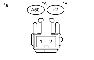
Text in Illustration*A
| for LHD
|
*B
| for RHD
|
*a
| Front view of wire harness connector
(to Clutch Switch Assembly)
|
| | REPAIR OR REPLACE HARNESS OR CONNECTOR |
|
|
| 3.CHECK HARNESS AND CONNECTOR (ECM - CLUTCH SWITCH ASSEMBLY) |
Disconnect the C45*1, C46*2 or A38*3 ECM connector.
- HINT:
- *1: for 1GR-FE (LHD)
- *2: for 1GR-FE (RHD) and 1VD-FTV (RHD)
- *3: for 1VD-FTV (LHD)
Disconnect the A50*1 or e2*2 clutch switch assembly connector.
- HINT:
- *1: for LHD
- *2: for RHD
Measure the resistance according to the value(s) in the table below.
- Standard Resistance:
for 1GR-FE (LHD)Tester Connection
| Condition
| Specified Condition
|
C45-27 (D) - A50-2
| Always
| Below 1 Ω
|
C45-27 (D) or A50-2 - Body ground
| Always
| 10 kΩ or higher
|
for 1GR-FE (RHD)Tester Connection
| Condition
| Specified Condition
|
C46-27 (D) - e2-2
| Always
| Below 1 Ω
|
C46-27 (D) or e2-2 - Body ground
| Always
| 10 kΩ or higher
|
for 1VD-FTV (LHD)Tester Connection
| Condition
| Specified Condition
|
A38-42 (CLSW) - A50-2
| Always
| Below 1 Ω
|
A38-42 (CLSW) or A50-2 - Body ground
| Always
| 10 kΩ or higher
|
for 1VD-FTV (RHD)Tester Connection
| Condition
| Specified Condition
|
C46-28 (CLSW) - e2-2
| Always
| Below 1 Ω
|
C46-28 (CLSW) or e2-2 - Body ground
| Always
| 10 kΩ or higher
|
- Result:
Result
| Proceed to
|
NG
| A
|
OK (for 1GR-FE)
| B
|
OK (for 1VD-FTV)
| C
|
| A |
|
|
|
| REPAIR OR REPLACE HARNESS OR CONNECTOR |
|