Dtc B2799 Engine Immobiliser System Malfunction
DESCRIPTION
WIRING DIAGRAM
INSPECTION PROCEDURE
CLEAR DTC
CHECK FOR DTC
CHECK BLOCKING SYSTEM
REREGISTER ECU COMMUNICATION ID
CLEAR DTC
CHECK FOR DTC
CHECK CONNECTION OF CONNECTOR
CHECK HARNESS AND CONNECTOR (SFI OR ECD COMMUNICATION LINE)
REPLACE ECM
REREGISTER ECU COMMUNICATION ID
CLEAR DTC
CHECK FOR DTC
REPLACE TRANSPONDER KEY ECU ASSEMBLY
REGISTER ECU COMMUNICATION ID
CLEAR DTC
CHECK FOR DTC
DTC B2799 Engine Immobiliser System Malfunction |
DESCRIPTION
This DTC is output when one of the following occurs: 1) the ECM detects errors in its own communications with the transponder key ECU assembly; 2) the ECM detects errors in the communication lines; or 3) the ECU communication ID between the transponder key ECU assembly and ECM is different and an engine start is attempted. Before troubleshooting for this DTC, make sure no transponder key ECU DTCs are present. If present, troubleshoot the transponder key ECU DTCs first.DTC Code
| DTC Detection Condition
| Trouble Area
| DTC Output Confirmation Operation
|
B2799
| Either condition is met (1 trip detection logic*1):
- A malfunction occurs in the communication or communication lines between the ECM and transponder key ECU assembly.
- A communication code cannot be verified during communication between the ECM and transponder key ECU assembly.
| - Harness or connector
- Transponder key ECU assembly
- ECM
- Telephone transceiver assembly*4
| Either condition is met:
- Within 10 seconds of an engine start operation being performed (with the shift lever in P and the brake pedal*2 or clutch pedal*3 depressed, turn the ignition switch to ON). If there is a malfunction, the engine stops (communication begins within 3 seconds of the engine start operation being performed, and DTCs are stored after 6 seconds).
- 10 seconds after the ignition switch is turned to ON after reconnecting the cable to the negative (-) battery terminal (communication begins within 3 seconds of the ignition switch being turned to ON, and DTCs are stored after 6 seconds).
|
- *1: Only output while a malfunction is present.
- *2: for Automatic Transmission
- *3: for Manual Transmission
- *4: w/ Blocking System
Vehicle Condition and Fail-safe Operation when Malfunction DetectedVehicle Condition when Malfunction Detected
| Fail-safe Operation when Malfunction Detected
|
Engine cannot be started.
| -
|
Related Data List and Active TestDTC Code
| Data List and Active Test
|
B2799
| -
|
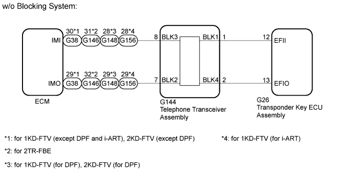
WIRING DIAGRAM
INSPECTION PROCEDURE
- NOTICE:
- The fixed 12 V power source voltage in the ECM is output through a resistance from terminal IMI. The transponder key ECU assembly grounds or does not ground this power source voltage accordingly.
- The fixed 12 V power source voltage in the transponder key ECU assembly is output through a resistance from terminal EFII. The ECM grounds or does not ground this power source voltage accordingly.
- When replacing the transponder key ECU assembly, ECM or telephone transceiver assembly (w/ Blocking System), refer to the Service Bulletin.
- After performing repairs, perform the operation that fulfills the DTC output confirmation operation, and then confirm that no DTCs are output again.
- HINT:
w/ Blocking System:
- When DTC B1587 and B2799 are output simultaneously, perform troubleshooting for DTC B2799 first.
- After troubleshooting for this DTC, make sure B2799 is not present. If present, troubleshoot the blocking system DTCs next.
Clear the DTCs (HILUX_TGN26 RM000000Z3I00TX.html).
Check for the DTCs (HILUX_TGN26 RM000000Z3I00TX.html).
- OK:
- DTC B2799 is not output.
ResultResult
| Proceed to
|
OK
| A
|
NG (w/ Blocking System)
| B
|
NG (w/o Blocking System)
| C
|
Check the blocking system setting.
- HINT:
- Check with the customer's contacted service provider to determine whether the blocking system is set.
- Request that the customer have the service provider unset the blocking system.
ResultResult
| Proceed to
|
Blocking system is unset.
| A
|
Blocking system is set
| B
|
| 4.REREGISTER ECU COMMUNICATION ID |
Reregister the ECU - ECM communication ID (Refer to Service Bulletin).
Clear the DTCs (HILUX_TGN26 RM000000Z3I00TX.html).
Check for the DTCs (HILUX_TGN26 RM000000Z3I00TX.html).
- OK:
- DTC B2799 is not output.
| OK |
|
|
|
| END (ECU COMMUNICATION ID IS NOT REGISTERED CORRECTLY) |
|
| 7.CHECK CONNECTION OF CONNECTOR |
Turn the ignition switch off.
Check that the connectors are properly connected to the ECM and transponder key ECU assembly.
- OK:
- Connectors are properly connected.
| | CONNECT CONNECTOR CORRECTLY |
|
|
| 8.CHECK HARNESS AND CONNECTOR (SFI OR ECD COMMUNICATION LINE) |
Disconnect the G26 transponder key ECU assembly connector.
Disconnect the G38*1, G88*2, G146*3, G148*4, G154*5 or G156*6 ECM connector.
- *1: for 1KD-FTV (except DPF and i-ART), 2KD-FTV (except DPF)
- *2: for 2TR-FE
- *3: for 2TR-FBE
- *4: 1KD-FTV (for DPF), 2KD-FTV (for DPF)
- *5: for 1GR-FE
- *6: for 1KD-FTV (for i-ART)
w/ Blocking System:
Disconnect the G144 telephone transceiver assembly connector.
Measure the resistance according to the value(s) in the table below.
- Standard Resistance:
- for 1KD-FTV (except DPF and i-ART), 2KD-FTV (except DPF) [w/o Blocking System]:
Tester Connection
| Condition
| Specified Condition
|
G26-13 (EFIO) - G38-30 (IMI)
| Always
| Below 1 Ω
|
G26-12 (EFII) - G38-29 (IMO)
| Always
| Below 1 Ω
|
G26-13 (EFIO) or G38-30 (IMI) - Body ground
| Always
| 10 kΩ or higher
|
G26-12 (EFII) or G38-29 (IMO) - Body ground
| Always
| 10 kΩ or higher
|
- for 1KD-FTV (except DPF and i-ART), 2KD-FTV (except DPF) [w/ Blocking System]:
Tester Connection
| Condition
| Specified Condition
|
G26-13 (EFIO) - G144-2 (BLK4)
| Always
| Below 1 Ω
|
G26-12 (EFII) - G144-1 (BLK1)
| Always
| Below 1 Ω
|
G144-8 (BLK3) - G38-30 (IMI)
| Always
| Below 1 Ω
|
G144-7 (BLK2) - G38-29 (IMO)
| Always
| Below 1 Ω
|
G26-13 (EFIO) or G144-2 (BLK4) - Body ground
| Always
| 10 kΩ or higher
|
G26-12 (EFII) or G144-1 (BLK1) - Body ground
| Always
| 10 kΩ or higher
|
G144-8 (BLK3) or G38-30 (IMI) - Body ground
| Always
| 10 kΩ or higher
|
G144-7 (BLK2) or G38-29 (IMO) - Body ground
| Always
| 10 kΩ or higher
|
- for 2TR-FE:
Tester Connection
| Condition
| Specified Condition
|
G26-13 (EFIO) - G88-16 (IMI)
| Always
| Below 1 Ω
|
G26-12 (EFII) - G88-15 (IMO)
| Always
| Below 1 Ω
|
G26-13 (EFIO) or G88-16 (IMI) - Body ground
| Always
| 10 kΩ or higher
|
G26-12 (EFII) or G88-15 (IMO) - Body ground
| Always
| 10 kΩ or higher
|
- for 2TR-FBE (w/o Blocking System):
Tester Connection
| Condition
| Specified Condition
|
G26-13 (EFIO) - G146-31 (IMI)
| Always
| Below 1 Ω
|
G26-12 (EFII) - G146-32 (IMO)
| Always
| Below 1 Ω
|
G26-13 (EFIO) or G146-31 (IMI) - Body ground
| Always
| 10 kΩ or higher
|
G26-12 (EFII) or G146-32 (IMO) - Body ground
| Always
| 10 kΩ or higher
|
- for 2TR-FBE (w/ Blocking System):
Tester Connection
| Condition
| Specified Condition
|
G26-13 (EFIO) - G144-2 (BLK4)
| Always
| Below 1 Ω
|
G26-12 (EFII) - G144-1 (BLK1)
| Always
| Below 1 Ω
|
G144-8 (BLK3) - G146-31 (IMI)
| Always
| Below 1 Ω
|
G144-7 (BLK2) - G146-32 (IMO)
| Always
| Below 1 Ω
|
G26-13 (EFIO) or G144-2 (BLK4) - Body ground
| Always
| 10 kΩ or higher
|
G26-12 (EFII) or G144-1 (BLK1) - Body ground
| Always
| 10 kΩ or higher
|
G144-8 (BLK3) or G146-31 (IMI) - Body ground
| Always
| 10 kΩ or higher
|
G144-7 (BLK2) or G146-32 (IMO) - Body ground
| Always
| 10 kΩ or higher
|
- for 1KD-FTV (for DPF), 2KD-FTV (for DPF) [w/o Blocking System]:
Tester Connection
| Condition
| Specified Condition
|
G26-13 (EFIO) - G148-28 (IMI)
| Always
| Below 1 Ω
|
G26-12 (EFII) - G148-29 (IMO)
| Always
| Below 1 Ω
|
G26-13 (EFIO) or G148-28 (IMI) - Body ground
| Always
| 10 kΩ or higher
|
G26-12 (EFII) or G148-29 (IMO) - Body ground
| Always
| 10 kΩ or higher
|
- for 1KD-FTV (for DPF), 2KD-FTV (for DPF) [w/ Blocking System]:
Tester Connection
| Condition
| Specified Condition
|
G26-13 (EFIO) - G144-2 (BLK4)
| Always
| Below 1 Ω
|
G26-12 (EFII) - G144-1 (BLK1)
| Always
| Below 1 Ω
|
G144-8 (BLK3) - G148-28 (IMI)
| Always
| Below 1 Ω
|
G144-7 (BLK2) - G148-29 (IMO)
| Always
| Below 1 Ω
|
G26-13 (EFIO) or G144-2 (BLK4) - Body ground
| Always
| 10 kΩ or higher
|
G26-12 (EFII) or G144-1 (BLK1) - Body ground
| Always
| 10 kΩ or higher
|
G144-8 (BLK3) or G148-28 (IMI) - Body ground
| Always
| 10 kΩ or higher
|
G144-7 (BLK2) or G148-29 (IMO) - Body ground
| Always
| 10 kΩ or higher
|
- for 1GR-FE:
Tester Connection
| Condition
| Specified Condition
|
G26-13 (EFIO) - G154-16 (IMI)
| Always
| Below 1 Ω
|
G26-12 (EFII) - G154-15 (IMO)
| Always
| Below 1 Ω
|
G26-13 (EFIO) or G154-16 (IMI) - Body ground
| Always
| 10 kΩ or higher
|
G26-12 (EFII) or G154-15 (IMO) - Body ground
| Always
| 10 kΩ or higher
|
- for 1KD-FTV (for i-ART) [w/o Blocking System]:
Tester Connection
| Condition
| Specified Condition
|
G26-13 (EFIO) - G156-28 (IMI)
| Always
| Below 1 Ω
|
G26-12 (EFII) - G156-29 (IMO)
| Always
| Below 1 Ω
|
G26-13 (EFIO) or G156-28 (IMI) - Body ground
| Always
| 10 kΩ or higher
|
G26-12 (EFII) or G156-29 (IMO) - Body ground
| Always
| 10 kΩ or higher
|
- for 1KD-FTV (for DPF), 2KD-FTV (for DPF) [w/ Blocking System]:
Tester Connection
| Condition
| Specified Condition
|
G26-13 (EFIO) - G144-2 (BLK4)
| Always
| Below 1 Ω
|
G26-12 (EFII) - G144-1 (BLK1)
| Always
| Below 1 Ω
|
G144-8 (BLK3) - G156-28 (IMI)
| Always
| Below 1 Ω
|
G144-7 (BLK2) - G156-29 (IMO)
| Always
| Below 1 Ω
|
G26-13 (EFIO) or G144-2 (BLK4) - Body ground
| Always
| 10 kΩ or higher
|
G26-12 (EFII) or G144-1 (BLK1) - Body ground
| Always
| 10 kΩ or higher
|
G144-8 (BLK3) or G156-28 (IMI) - Body ground
| Always
| 10 kΩ or higher
|
G144-7 (BLK2) or G156-29 (IMO) - Body ground
| Always
| 10 kΩ or higher
|
Measure the voltage according to the value(s) in the table below.
- Standard Voltage:
- for 1KD-FTV (except DPF and i-ART), 2KD-FTV (except DPF) [w/o Blocking System]:
Tester Connection
| Condition
| Specified Condition
|
G26-13 (EFIO) or G38-30 (IMI) - Body ground
| Always
| Below 1 V
|
G26-12 (EFII) or G38-29 (IMO) - Body ground
| Always
| Below 1 V
|
- for 1KD-FTV (except DPF and i-ART), 2KD-FTV (except DPF) [w/ Blocking System]:
Tester Connection
| Condition
| Specified Condition
|
G26-13 (EFIO) or G144-2 (BLK4) - Body ground
| Always
| Below 1 V
|
G26-12 (EFII) or G144-1 (BLK1) - Body ground
| Always
| Below 1 V
|
G144-8 (BLK3) or G38-30 (IMI) - Body ground
| Always
| Below 1 V
|
G144-7 (BLK2) or G38-29 (IMO) - Body ground
| Always
| Below 1 V
|
- for 2TR-FE:
Tester Connection
| Condition
| Specified Condition
|
G26-13 (EFIO) or G88-16 (IMI) - Body ground
| Always
| Below 1 V
|
G26-12 (EFII) or G88-15 (IMO) - Body ground
| Always
| Below 1 V
|
- for 2TR-FBE (w/o Blocking System):
Tester Connection
| Condition
| Specified Condition
|
G26-13 (EFIO) or G146-31 (IMI) - Body ground
| Always
| Below 1 V
|
G26-12 (EFII) or G146-32 (IMO) - Body ground
| Always
| Below 1 V
|
- for 2TR-FBE (w/ Blocking System):
Tester Connection
| Condition
| Specified Condition
|
G26-13 (EFIO) or G144-2 (BLK4) - Body ground
| Always
| Below 1 V
|
G26-12 (EFII) or G144-1 (BLK1) - Body ground
| Always
| Below 1 V
|
G144-8 (BLK3) or G146-31 (IMI) - Body ground
| Always
| Below 1 V
|
G144-7 (BLK2) or G146-32 (IMO) - Body ground
| Always
| Below 1 V
|
- for 1KD-FTV (for DPF), 2KD-FTV (for DPF) [w/o Blocking System]:
Tester Connection
| Condition
| Specified Condition
|
G26-13 (EFIO) or G148-28 (IMI) - Body ground
| Always
| Below 1 V
|
G26-12 (EFII) or G148-29 (IMO) - Body ground
| Always
| Below 1 V
|
- for 1KD-FTV (for DPF), 2KD-FTV (for DPF) [w/ Blocking System]:
Tester Connection
| Condition
| Specified Condition
|
G26-13 (EFIO) or G144-2 (BLK4) - Body ground
| Always
| Below 1 V
|
G26-12 (EFII) or G144-1 (BLK1) - Body ground
| Always
| Below 1 V
|
G144-8 (BLK3) or G148-28 (IMI) - Body ground
| Always
| Below 1 V
|
G144-7 (BLK2) or G148-29 (IMO) - Body ground
| Always
| Below 1 V
|
- for 1GR-FE:
Tester Connection
| Condition
| Specified Condition
|
G26-13 (EFIO) or G154-16 (IMI) - Body ground
| Always
| Below 1 V
|
G26-12 (EFII) or G154-15 (IMO) - Body ground
| Always
| Below 1 V
|
- for 1KD-FTV (for i-ART) [w/o Blocking System]:
Tester Connection
| Condition
| Specified Condition
|
G26-13 (EFIO) or G156-28 (IMI) - Body ground
| Always
| Below 1 V
|
G26-12 (EFII) or G156-29 (IMO) - Body ground
| Always
| Below 1 V
|
- for 1KD-FTV (for i-ART) [w/ Blocking System]:
Tester Connection
| Condition
| Specified Condition
|
G26-13 (EFIO) or G144-2 (BLK4) - Body ground
| Always
| Below 1 V
|
G26-12 (EFII) or G144-1 (BLK1) - Body ground
| Always
| Below 1 V
|
G144-8 (BLK3) or G156-28 (IMI) - Body ground
| Always
| Below 1 V
|
G144-7 (BLK2) or G156-29 (IMO) - Body ground
| Always
| Below 1 V
|
| | REPAIR OR REPLACE HARNESS OR CONNECTOR |
|
|
Temporarily replace the ECM with a new one.
- for 1KD-FTV: HILUX_TGN26 RM000000VW2024X.html
- for 2KD-FTV: HILUX_TGN26 RM0000013Z001HX.html
- for 2TR-FE: HILUX_TGN26 RM000000VW202LX.html
- for 2TR-FBE: HILUX_TGN26 RM000000VW2024X.html
- for 1GR-FE: HILUX_TGN26 RM000000VW202KX.html
| 10.REREGISTER ECU COMMUNICATION ID |
Reregister the ECU - ECM communication ID (Refer to Service Bulletin).
Clear the DTCs (HILUX_TGN26 RM000000Z3I00TX.html).
Check for the DTCs (HILUX_TGN26 RM000000Z3I00TX.html).
- OK:
- DTC B2799 is not output.
ResultResult
| Proceed to
|
OK
| A
|
NG (w/o Blocking System)
| B
|
NG (w/ Blocking System)
| C
|
| | REPLACE TRANSPONDER KEY ECU ASSEMBLY |
|
|
| |
|
| 13.REPLACE TRANSPONDER KEY ECU ASSEMBLY |
Temporarily replace the transponder key ECU assembly with a new one (Refer to Service Bulletin).
| 14.REGISTER ECU COMMUNICATION ID |
Reregister the ECU - ECM communication ID (Refer to Service Bulletin).
Clear the DTCs (HILUX_TGN26 RM000000Z3I00TX.html).
Check for DTCs (HILUX_TGN26 RM000000Z3I00TX.html).
- OK:
- DTC B2799 is not output.
| | REPLACE TELEPHONE TRANSCEIVER ASSEMBLY |
|
|
| OK |
|
|
|
| END (TRANSPONDER KEY ECU IS DEFECTIVE) |
|