Engine Assembly (W/O Glow Plug Controller) Removal
PRECAUTION
DISCONNECT CABLE FROM NEGATIVE BATTERY TERMINAL
REMOVE HOOD SUB-ASSEMBLY
REMOVE NO. 1 ENGINE UNDER COVER
REMOVE NO. 2 ENGINE UNDER COVER
DRAIN ENGINE OIL
DRAIN ENGINE COOLANT
DRAIN TRANSMISSION OIL (for Manual Transmission)
DRAIN TRANSMISSION FLUID (for Automatic Transmission)
DRAIN POWER STEERING FLUID
REMOVE BATTERY CLAMP SUB-ASSEMBLY
REMOVE BATTERY
REMOVE BATTERY TRAY
REMOVE AIR CLEANER ASSEMBLY
REMOVE INTERCOOLER ASSEMBLY WITH INTAKE AIR CONNECTOR
REMOVE RADIATOR ASSEMBLY
REMOVE STARTER ASSEMBLY
REMOVE FRONT EXHAUST PIPE ASSEMBLY
REMOVE FRONT PROPELLER SHAFT ASSEMBLY (for 4WD)
REMOVE PROPELLER WITH CENTER BEARING SHAFT ASSEMBLY
DISCONNECT HEATER HOSE
DISCONNECT PRESSURE FEED TUBE ASSEMBLY
DISCONNECT FUEL HOSE
DISCONNECT UNION TO CONNECTOR TUBE HOSE
REMOVE GLOVE COMPARTMENT DOOR ASSEMBLY
DISCONNECT WIRE HARNESS
DISCONNECT COOLER COMPRESSOR ASSEMBLY (w/ Air Conditioning System)
REMOVE MANUAL TRANSMISSION ASSEMBLY (for Manual Transmission)
REMOVE DRIVE PLATE AND TORQUE
CONVERTER SETTING BOLT (for Automatic Transmission)
REMOVE AUTOMATIC TRANSMISSION ASSEMBLY (for Automatic Transmission)
REMOVE REAR NO. 1 ENGINE MOUNTING INSULATOR
REMOVE CLUTCH COVER ASSEMBLY (for Manual Transmission)
REMOVE CLUTCH DISC ASSEMBLY (for Manual Transmission)
REMOVE FLYWHEEL SUB-ASSEMBLY (for Manual Transmission)
REMOVE PUMP IMPELLER DRIVE PLATE (for Automatic Transmission)
REMOVE REAR END PLATE
INSTALL ENGINE HANGERS
REMOVE ENGINE ASSEMBLY
INSTALL ENGINE TO ENGINE STAND
REMOVE ENGINE WIRE
REMOVE FRONT ENGINE MOUNTING INSULATOR
Engine Assembly (W/O Glow Plug Controller) -- Removal |
- NOTICE:
- When replacing the injectors (including shuffling the injectors between the cylinders), common rail or cylinder head, it is necessary to replace the injection pipes with new ones.
- When replacing the fuel supply pump, common rail, cylinder block, cylinder head, cylinder head gasket or timing gear case, it is necessary to replace the fuel inlet pipe with a new one.
- After removing the injection pipes, clean them with a brush and compressed air.
- NOTICE:
- After turning the ignition switch off, waiting time may be required before disconnecting the cable from the battery terminal. Therefore, make sure to read the disconnecting the cable from the battery terminal notice before proceeding with work (HILUX_TGN26 RM000004QR1003X.html).
| 2. DISCONNECT CABLE FROM NEGATIVE BATTERY TERMINAL |
- NOTICE:
- When disconnecting the cable, some systems need to be initialized after the cable is reconnected (HILUX_TGN26 RM000004QR3003X.html).
| 3. REMOVE HOOD SUB-ASSEMBLY |
Disconnect the washer nozzle hose.
Remove the 4 bolts and hood.
| 4. REMOVE NO. 1 ENGINE UNDER COVER |
| 5. REMOVE NO. 2 ENGINE UNDER COVER |
Remove the oil filler cap.
Remove the oil pan drain plug and gasket, and then drain the engine oil into a container.
Wipe the oil pan and drain plug.
Install a new gasket and the oil pan drain plug.
- Torque:
- 34 N*m{347 kgf*cm, 25 ft.*lbf}
- CAUTION:
- Do not remove the radiator reservoir cap while the engine and radiator are still hot. Pressurized, hot engine coolant and steam may be released and cause serious burns.
Loosen the radiator drain cock plug.
- HINT:
- Collect the coolant in a container and dispose of it according to the regulations in your area.
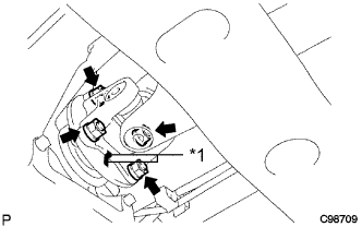
Drain the coolant by removing the radiator reservoir cap and, using a wrench, remove the vent plug.
Loosen the cylinder block drain cock plug.
Text in Illustration*1
| Radiator Reservoir
| *2
| Radiator Reservoir Cap
|
*3
| Vent Plug
| *4
| Cylinder Block Drain Cock Plug
|
*5
| Radiator Drain Cock Plug
| -
| -
|
| 8. DRAIN TRANSMISSION OIL (for Manual Transmission) |
Remove the filler plug and gasket.
Remove the drain plug and gasket to drain the manual transmission oil.
Install a new gasket and the drain plug.
- Torque:
- 37 N*m{377 kgf*cm, 27 ft.*lbf}
| 9. DRAIN TRANSMISSION FLUID (for Automatic Transmission) |
Remove the drain plug and gasket, and drain ATF.
Install a new gasket and the drain plug.
- Torque:
- 20 N*m{205 kgf*cm, 15 ft.*lbf}
| 10. DRAIN POWER STEERING FLUID |
| 11. REMOVE BATTERY CLAMP SUB-ASSEMBLY |
Remove the bolt, nut and battery clamp.
| 14. REMOVE AIR CLEANER ASSEMBLY |
Disconnect the mass air flow meter connector.
Loosen the hose clamp.
Remove the 2 bolts and air cleaner.
| 15. REMOVE INTERCOOLER ASSEMBLY WITH INTAKE AIR CONNECTOR |
(HILUX_TGN26 RM0000015B9015X.html)
| 16. REMOVE RADIATOR ASSEMBLY |
(HILUX_TGN26 RM00000144G01HX.html)
| 17. REMOVE STARTER ASSEMBLY |
(HILUX_TGN26 RM0000013XL02LX.html)
| 18. REMOVE FRONT EXHAUST PIPE ASSEMBLY |
(HILUX_TGN26 RM00000121301DX.html)
| 19. REMOVE FRONT PROPELLER SHAFT ASSEMBLY (for 4WD) |
Place matchmarks on the propeller shaft flange and differential flange.
Text in Illustration*1
| Matchmark
|
Remove the 4 nuts, 4 bolts and 4 washers and disconnect the propeller shaft.
Place matchmarks on the propeller shaft flange and transfer flange.
Text in Illustration*1
| Matchmark
|
Remove the 4 nuts, 4 washers and front propeller shaft.
| 20. REMOVE PROPELLER WITH CENTER BEARING SHAFT ASSEMBLY |
(HILUX_TGN26 RM000000ZZ301QX.html)
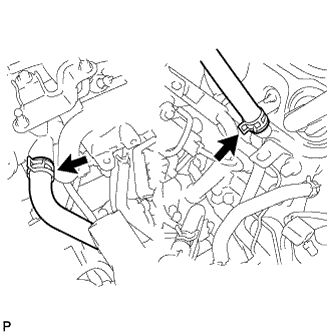
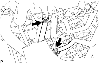
| 21. DISCONNECT HEATER HOSE |
Disconnect the 2 heater hoses.
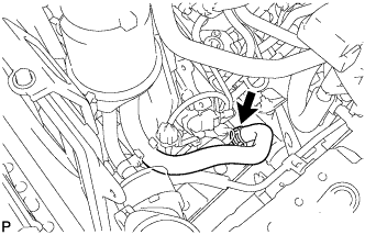
| 22. DISCONNECT PRESSURE FEED TUBE ASSEMBLY |
Disconnect the oil reservoir to pump hose.
Disconnect the pressure feed tube.
Disconnect the 2 fuel hoses.
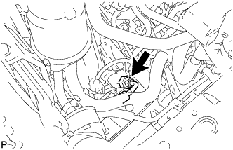
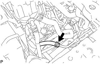
| 24. DISCONNECT UNION TO CONNECTOR TUBE HOSE |
Disconnect the union to connector tube hose.
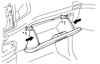
| 25. REMOVE GLOVE COMPARTMENT DOOR ASSEMBLY |
Slightly bend the upper part of the glove compartment door to release the 2 stoppers and open the glove compartment door until it is horizontal.
Text in Illustration*1
| Stopper
|
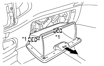
Pull the glove compartment door toward the rear of the vehicle to detach the 2 hinges and remove the glove compartment door.
Text in Illustration*1
| Hinge
|
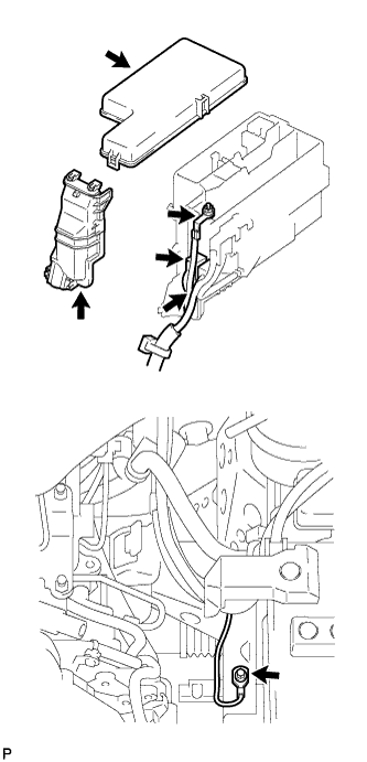
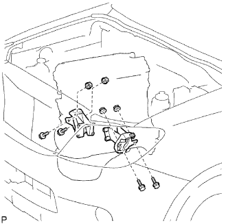
| 26. DISCONNECT WIRE HARNESS |
Remove the upper relay block cover.
Remove the side relay block cover.
Remove the nut and disconnect the engine room junction block wire.
Disconnect the 2 engine room junction block connectors.
Remove the bolt and disconnect the ground cable.
Remove the 2 nuts, detach the clamp and disconnect the wire harness.
Disconnect the 3 injector driver connectors.
Disconnect the turbo motor driver connector.
for 4WD:
Disconnect the 4WD control ECU connector.
for Automatic Transmission:
Disconnect the 3 TCM connectors.
Disconnect the 4 ECM connectors.
| 27. DISCONNECT COOLER COMPRESSOR ASSEMBLY (w/ Air Conditioning System) |
Remove the 4 bolts and disconnect the cooler compressor.
- HINT:
- It is not necessary to completely remove the cooler compressor. With the hoses connected to the cooler compressor, hang the cooler compressor on the vehicle body with a rope.
| 28. REMOVE MANUAL TRANSMISSION ASSEMBLY (for Manual Transmission) |
- for 2WD: (HILUX_TGN26 RM0000011B200RX.html)
- for 4WD: (HILUX_TGN26 RM0000011AL00IX.html)
| 29. REMOVE DRIVE PLATE AND TORQUE
CONVERTER SETTING BOLT (for Automatic Transmission) |
| 30. REMOVE AUTOMATIC TRANSMISSION ASSEMBLY (for Automatic Transmission) |
(HILUX_TGN26 RM0000010NV01KX.html)
| 31. REMOVE REAR NO. 1 ENGINE MOUNTING INSULATOR |
- HINT:
- Perform this procedure only when replacement of the rear No. 1 engine mounting insulator is necessary.
Remove the 4 bolts and rear No. 1 engine mounting insulator.
| 32. REMOVE CLUTCH COVER ASSEMBLY (for Manual Transmission) |
Place matchmarks on the clutch cover and flywheel.
Text in Illustration*1
| Matchmark
|
Loosen each set bolt one turn at a time until spring tension is released.
Remove the 6 set bolts and pull off the clutch cover.
- NOTICE:
- Do not drop the clutch disc.
| 33. REMOVE CLUTCH DISC ASSEMBLY (for Manual Transmission) |
- NOTICE:
- Keep the lining part of the clutch disc, the pressure plate and the surface of the flywheel away from oil and foreign matter.
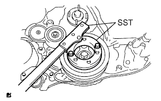
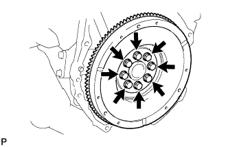
| 34. REMOVE FLYWHEEL SUB-ASSEMBLY (for Manual Transmission) |
Using SST, hold the crankshaft pulley.
- SST
- 09213-58014
09330-00021
Remove the 8 bolts and flywheel.
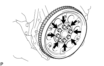
| 35. REMOVE PUMP IMPELLER DRIVE PLATE (for Automatic Transmission) |
Using SST, hold the crankshaft pulley.
- SST
- 09213-58014
09330-00021
Remove the 8 bolts, rear drive plate spacer, pump impeller drive plate and flywheel.
| 36. REMOVE REAR END PLATE |
Remove the bolt and rear end plate.
| 37. INSTALL ENGINE HANGERS |
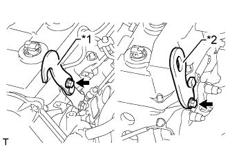
Install a No. 1 engine hanger and No. 2 engine hanger with 2 bolts as shown in the illustration.
- Torque:
- for No. 1 engine hanger:
- 25 N*m{255 kgf*cm, 18 ft.*lbf}
- for No. 2 engine hanger:
- 60 N*m{612 kgf*cm, 44 ft.*lbf}
Text in Illustration*1
| No. 1 Engine Hanger
|
*2
| No. 2 Engine Hanger
|
- NOTICE:
- Install the engine hangers with new bolts.
- HINT:
- Part No.
No. 1 Engine Hanger
| 12284-30020
|
No. 2 Engine Hanger
| 12282-67030
|
Bolt
| 91552-81014 and 91642-81030
|
| 38. REMOVE ENGINE ASSEMBLY |
Attach an engine sling device and hang the engine with a chain block.
Remove the 4 bolts and 4 nuts.
Remove the engine by operating the engine sling device and chain block.
| 39. INSTALL ENGINE TO ENGINE STAND |
Install the engine to an engine stand with bolts.
Remove the 2 bolts and 2 engine hangers.
Remove the engine wire from the engine.
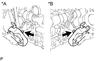
| 41. REMOVE FRONT ENGINE MOUNTING INSULATOR |
Remove the 2 nuts and 2 front engine mounting insulators.
Text in Illustration*A
| RH Side
|
*B
| LH Side
|