Valve Clearance -- Adjustment |
| 1. PRECAUTION |
- NOTICE:
- After turning the ignition switch off, waiting time may be required before disconnecting the cable from the battery terminal. Therefore, make sure to read the disconnecting the cable from the battery terminal notice before proceeding with work (HILUX_TGN26 RM000004QR1006X.html).
| 2. DISCONNECT CABLE FROM NEGATIVE BATTERY TERMINAL |
- NOTICE:
- When disconnecting the cable, some systems need to be initialized after the cable is reconnected (HILUX_TGN26 RM000004QR300CX.html).
| 3. REMOVE INTAKE AIR SURGE TANK |
| 4. REMOVE IGNITION COIL ASSEMBLY |
Disconnect the 6 ignition coil connectors.
Remove the 6 bolts and 6 ignition coils.
| 5. REMOVE CYLINDER HEAD COVER SUB-ASSEMBLY |
Remove the 10 bolts, 3 seal washers, 2 nuts, cylinder head cover and gasket.
Text in Illustration 
Bolt 
Nut
 |
| 6. REMOVE CYLINDER HEAD COVER SUB-ASSEMBLY LH |
Remove the 10 bolts, 3 seal washers, 2 nuts, cylinder head cover and gasket.
Text in Illustration Bolt Nut
 |
| 7. SET NO. 1 CYLINDER TO TDC/COMPRESSION |
Turn the crankshaft pulley and align its groove with the "0" timing mark of the timing chain cover.
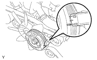 |
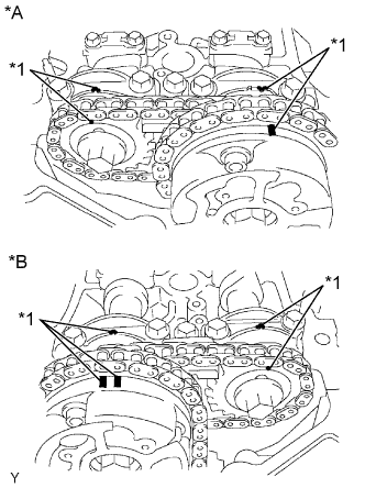
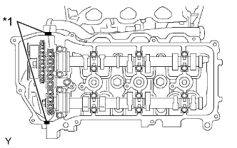
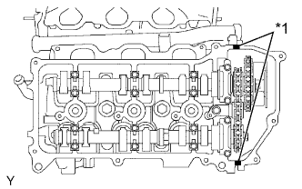
Check that the timing marks of the camshaft timing gears are aligned with the timing marks of the bearing cap as shown in the illustration.
If not, turn the crankshaft 1 complete revolution (360°) and align the timing marks as above.Text in Illustration *A for Bank 1 *B for Bank 2 *1 Timing Mark
 |
| 8. INSPECT VALVE CLEARANCE |
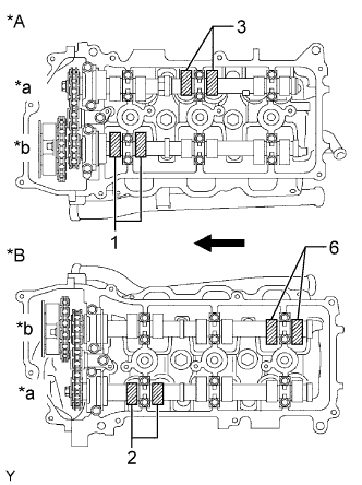
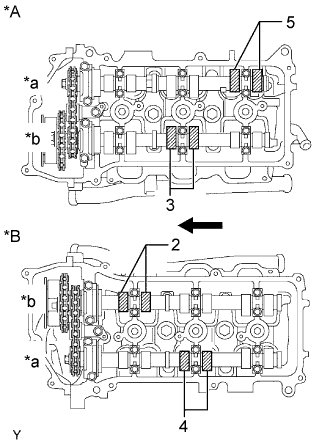
Check the valves indicated in the illustration.
Using a feeler gauge, measure the clearance between the valve lifter and camshaft.
- Standard Valve Clearance (Cold):
Item Specified Condition Intake 0.15 to 0.25 mm (0.00591 to 0.00984 in.) Exhaust 0.29 to 0.39 mm (0.0114 to 0.0154 in.)
Text in Illustration *A for Bank 1 *B for Bank 2 *a Exhaust Side *b Intake Side Engine Front Record the out-of-specification valve clearance measurements. They will be used later to determine the required replacement valve lifter.
 |
Turn the crankshaft 2/3 of a revolution (240°).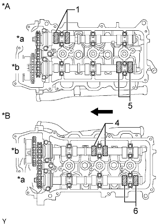
Check the valves indicated in the illustration.
Using a feeler gauge, measure the clearance between the valve lifter and camshaft.
- Standard Valve Clearance (Cold):
Item Specified Condition Intake 0.15 to 0.25 mm (0.00591 to 0.00984 in.) Exhaust 0.29 to 0.39 mm (0.0114 to 0.0154 in.)
Text in Illustration *A for Bank 1 *B for Bank 2 *a Exhaust Side *b Intake Side Engine Front Record the out-of-specification valve clearance measurements. They will be used later to determine the required replacement valve lifter.
| 9. ADJUST VALVE CLEARANCE |
Remove the camshaft (HILUX_TGN26 RM0000015D100FX.html).
Remove the 24 valve lifters from the cylinder head and cylinder head LH.
Determine the size of the valve lifter to be installed according to the following formulas or charts.
Using a micrometer, measure the thickness of the removed lifter.
Calculate the thickness of a new lifter so that the valve clearance is within the specified range.
- T:
- Thickness of removed lifter
- A:
- Measured valve clearance
- N:
- Thickness of new lifter
- Intake:
- N = T + (A - 0.20 mm (0.00787 in.))
- Exhaust:
- N = T + (A - 0.34 mm (0.0131 in.))
Select a new lifter with a thickness as close as possible to the calculated value.
- HINT:
- Lifters are available in 35 sizes in increments of 0.020 mm (0.000787 in.), from 5.060 mm (0.1992 in.) to 5.740 mm (0.2260 in.).

Text in Illustration *1 Valve Lifter Selection Chart (Intake) *2 Measured Clearance
mm (in.)*3 Installed Lifter Thickness
mm (in.)- - - Intake valve clearance (Cold):
- 0.15 to 0.25 mm (0.00591 to 0.00984 in.)
- EXAMPLE:
- The 5.250 mm (0.2067 in.) lifter is installed, and the measured clearance is 0.400 mm (0.0157 in.). Replace the 5.250 mm (0.2067 in.) lifter with a No. 46 lifter.
- New Lifter Thickness:
Lifter No. Thickness Lifter No. Thickness Lifter No. Thickness 06 5.060 mm (0.1992 in.) 30 5.300 mm (0.2087 in.) 54 5.540 mm (0.2181 in.) 08 5.080 mm (0.2000 in.) 32 5.320 mm (0.2094 in.) 56 5.560 mm (0.2189 in.) 10 5.100 mm (0.2008 in.) 34 5.340 mm (0.2102 in.) 58 5.580 mm (0.2197 in.) 12 5.120 mm (0.2016 in.) 36 5.360 mm (0.2110 in.) 60 5.600 mm (0.2205 in.) 14 5.140 mm (0.2024 in.) 38 5.380 mm (0.2118 in.) 62 5.620 mm (0.2213 in.) 16 5.160 mm (0.2031 in.) 40 5.400 mm (0.2126 in.) 64 5.640 mm (0.2220 in.) 18 5.180 mm (0.2039 in.) 42 5.420 mm (0.2134 in.) 66 5.660 mm (0.2228 in.) 20 5.200 mm (0.2047 in.) 44 5.440 mm (0.2142 in.) 68 5.680 mm (0.2236 in.) 22 5.220 mm (0.2055 in.) 46 5.460 mm (0.2150 in.) 70 5.700 mm (0.2244 in.) 24 5.240 mm (0.2063 in.) 48 5.480 mm (0.2157 in.) 72 5.720 mm (0.2252 in.) 26 5.260 mm (0.2071 in.) 50 5.500 mm (0.2165 in.) 74 5.740 mm (0.2260 in.) 28 5.280 mm (0.2079 in.) 52 5.520 mm (0.2173 in.) - -

Text in Illustration *1 Valve Lifter Selection Chart (Exhaust) *2 Measured Clearance
mm (in.)*3 Installed Lifter Thickness
mm (in.)- - - Exhaust valve clearance (Cold):
- 0.29 to 0.39 mm (0.0114 to 0.0154 in.)
- EXAMPLE:
- The 5.340 mm (0.210 in.) lifter is installed, and the measured clearance is 0.480 mm (0.0189 in.). Replace the 5.340 mm (0.210 in.) lifter with a No. 48 lifter.
- New Lifter Thickness:
Lifter No. Thickness Lifter No. Thickness Lifter No. Thickness 06 5.060 mm (0.1992 in.) 30 5.300 mm (0.2087 in.) 54 5.540 mm (0.2181 in.) 08 5.080 mm (0.2000 in.) 32 5.320 mm (0.2094 in.) 56 5.560 mm (0.2189 in.) 10 5.100 mm (0.2008 in.) 34 5.340 mm (0.2102 in.) 58 5.580 mm (0.2197 in.) 12 5.120 mm (0.2016 in.) 36 5.360 mm (0.2110 in.) 60 5.600 mm (0.2205 in.) 14 5.140 mm (0.2024 in.) 38 5.380 mm (0.2118 in.) 62 5.620 mm (0.2213 in.) 16 5.160 mm (0.2031 in.) 40 5.400 mm (0.2126 in.) 64 5.640 mm (0.2220 in.) 18 5.180 mm (0.2039 in.) 42 5.420 mm (0.2134 in.) 66 5.660 mm (0.2228 in.) 20 5.200 mm (0.2047 in.) 44 5.440 mm (0.2142 in.) 68 5.680 mm (0.2236 in.) 22 5.220 mm (0.2055 in.) 46 5.460 mm (0.2150 in.) 70 5.700 mm (0.2244 in.) 24 5.240 mm (0.2063 in.) 48 5.480 mm (0.2157 in.) 72 5.720 mm (0.2252 in.) 26 5.260 mm (0.2071 in.) 50 5.500 mm (0.2165 in.) 74 5.740 mm (0.2260 in.) 28 5.280 mm (0.2079 in.) 52 5.520 mm (0.2173 in.) - -
Install the camshaft (HILUX_TGN26 RM0000015CY00IX.html).
Check the valve clearance again.
If the result is not as specified, adjust the valve clearance.
| 10. INSTALL CYLINDER HEAD COVER SUB-ASSEMBLY LH |
Remove any old packing (FIPG) material and be careful not to drop any oil on the contact surfaces of the cylinder head, timing chain cover and cylinder head cover.
Apply seal packing as shown in the illustration.
- Seal packing:
- Toyota Genuine Seal Packing Black, Three Bond 1207B or equivalent
- Standard seal diameter:
- 2.0 to 3.0 mm (0.0787 to 0.118 in.)
Text in Illustration *1 Seal Packing - NOTICE:
- Install the cylinder head cover within 3 minutes after applying seal packing. After installing it, cylinder head cover bolts and nuts must be tightened within 15 minutes. Otherwise the seal packing must be removed and reapplied.
 |
Install a new gasket to the cylinder head cover.
Install a new seal washers to the bolts.
Temporarily install the cylinder head cover with the 10 bolts and 2 nuts. Tighten the bolts and nuts uniformly in several steps.
- Torque:
- for bolt A:
- 10 N*m{102 kgf*cm, 7 ft.*lbf}
- for bolt B and nut:
- 9.0 N*m{92 kgf*cm, 80 in.*lbf}
Text in Illustration Bolt A Bolt B 
Nut
 |
| 11. INSTALL CYLINDER HEAD COVER SUB-ASSEMBLY |
Remove any old packing (FIPG) material and be careful not to drop any oil on the contact surfaces of the cylinder head, timing chain cover and cylinder head cover.
Apply seal packing as shown in the illustration.
- Seal packing:
- Toyota Genuine Seal Packing Black, Three Bond 1207B or equivalent
- Standard seal diameter:
- 2.0 to 3.0 mm (0.0787 to 0.118 in.)
Text in Illustration *1 Seal Packing - NOTICE:
- Install the cylinder head cover within 3 minutes after applying seal packing. After installing it, cylinder head cover bolts and nuts must be tightened within 15 minutes. Otherwise the seal packing must be removed and reapplied.
 |
Install a new gasket to the cylinder head cover.
Install a new seal washers to the bolts.
Temporarily install the cylinder head cover with the 10 bolts and 2 nuts. Tighten the bolts and nuts uniformly in several steps.
- Torque:
- for bolt A:
- 10 N*m{102 kgf*cm, 7 ft.*lbf}
- for bolt B and nut:
- 9.0 N*m{92 kgf*cm, 80 in.*lbf}
Text in Illustration Bolt A Bolt B Nut
 |
| 12. INSTALL IGNITION COIL ASSEMBLY |
Install the 6 ignition coils with the 6 bolts.
- Torque:
- 10 N*m{102 kgf*cm, 7 ft.*lbf}
Connect the 6 ignition coil connectors.
| 13. INSTALL INTAKE AIR SURGE TANK |
| 14. CONNECT CABLE TO NEGATIVE BATTERY TERMINAL |
- NOTICE:
- When disconnecting the cable, some systems need to be initialized after the cable is reconnected (HILUX_TGN26 RM000004QR300CX.html).
| 15. INSPECT IGNITION TIMING |
- NOTICE:
- Turn all electrical systems off.
Warm up the engine.
When using the intelligent tester:
Connect the intelligent tester to the DLC3.
Enter the following menus: Powertrain / Engine and ECT / Data List / All Data / IGN Advance.
Inspect the ignition timing during idling.
- Standard ignition timing:
- 7 to 24° BTDC @ idle (transmission in neutral and A/C switch off)
Check that the ignition timing advances immediately when the engine speed is increased.
When not using the intelligent tester:
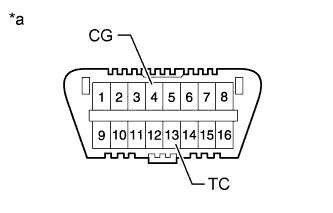
Using SST, connect terminals 13 (TC) and 4 (CG) of the DLC3.
- SST
- 09843-18040
Text in Illustration *a Front view of DLC3 - NOTICE:
- Be sure not to improperly connect the terminals. This may damage the engine.
Connect the tester probe of a timing light to the wire of the ignition coil connector for the No. 1 cylinder.
- NOTICE:
- Use a timing light that detects primary signals.
- After the inspection, be sure to wrap the wire harness with tape.
Inspect the ignition timing during idling.
- Standard ignition timing:
- 8 to 12° BTDC @ idle (transmission in neutral and A/C switch off)
Remove SST from the DLC3.
Inspect the ignition timing during idling.
- Standard ignition timing:
- 7 to 24° BTDC @ idle (transmission in neutral and A/C switch off)
Disconnect the timing light from the engine.