Dtc P1264 Vn Turbo Controller Malfunction
DESCRIPTION
WIRING DIAGRAM
INSPECTION PROCEDURE
CHECK TURBO MOTOR DRIVER
CHECK HARNESS AND CONNECTOR (TURBO MOTOR DRIVER - ECM)
INSPECT ECM (VNTO VOLTAGE)
INSPECT ECM (VNTI VOLTAGE)
REPAIR OR REPLACE HARNESS OR CONNECTOR
REPLACE ECM
REPLACE TURBO MOTOR DRIVER
CONFIRM WHETHER MALFUNCTION HAS BEEN SUCCESSFULLY REPAIRED
DTC P1264 VN Turbo Controller Malfunction |
DESCRIPTION
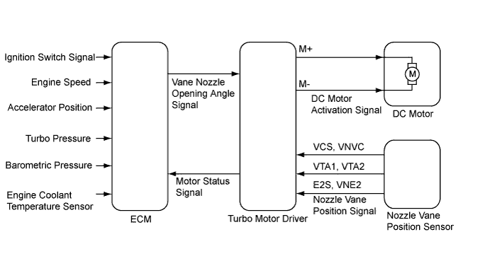
The turbocharger system is comprised of the Variable Nozzle (VN) type turbocharger, the turbo motor driver and ECM.The turbocharger has a nozzle vane which opens and closes to control the volume of the exhaust gas flowing into the turbine. This, in turn, controls the boost pressure, when the nozzle vane moves towards the closing direction, the pressure increases. When the vane moves towards the opening direction, the pressure decreases.The turbocharger actuator, which consists of the DC motor and the nozzle vane position sensor, is built on the turbocharger sub-assembly, and activates the nozzle vane. The nozzle vane position sensor detects the opening angle of the nozzle vane. The turbo motor driver receives an opening angle request from the ECM and a nozzle vane position signal from the nozzle vane position sensor. Based on these signals, the turbo motor driver operates the DC motor and adjusts the nozzle vane opening angle. The turbo motor driver sends the status as a turbo driver status signal to the ECMThe ECM sends a target nozzle vane position signal to the turbo motor driver to obtain the nozzle vane position for the optimal boost pressure in accordance with the driving conditions.P1264DTC Detection Drive Pattern
| DTC Detection Condition
| Trouble Area
|
Ignition switch to ON for 5 seconds
| When communication error occurs between turbo motor and ECM
(1 trip detection logic)
| - Turbo motor driver
- Open or short in turbo motor driver circuit
- Turbo motor driver ground problem
- ECM
|
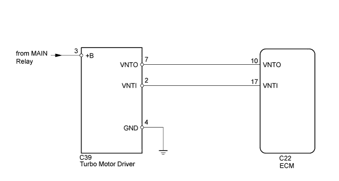
WIRING DIAGRAM
INSPECTION PROCEDURE
- NOTICE:
- After replacing the ECM, the new ECM needs registration (HILUX_TGN26 RM0000012XK07GX.html) and initialization (HILUX_TGN26 RM000000TIN04EX.html).
- HINT:
- Read freeze frame data using the intelligent tester. Freeze frame data records the engine condition when malfunctions are detected. When troubleshooting, freeze frame data can help determine if the vehicle was moving or stationary, if the engine was warmed up or not, and other data from the time the malfunction occurred.
- Excessive electrical noise, such as from wireless radios or electrical modifications, may cause a DTC output.
| 1.CHECK TURBO MOTOR DRIVER |
Disconnect the turbo motor driver connector.
Turn the ignition switch to ON.
Measure the voltage according to the value(s) in the table below.
- Standard Voltage:
Tester Connection
| Condition
| Specified Condition
|
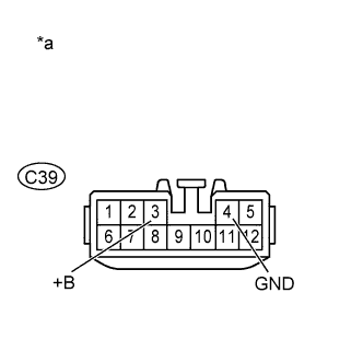
C39-3 (+B) - C39-4 (GND)
| Always
| 11 to 14 V
|
Measure the resistance according to the value(s) in the table below.
- Standard Resistance:
Tester Connection
| Condition
| Specified Condition
|
C39-4 (GND) - Body ground
| Always
| Below 1 Ω
|
Text in Illustration*a
| Front view of wire harness connector
(to Turbo Motor Driver)
|
Reconnect the turbo motor driver connector.
| 2.CHECK HARNESS AND CONNECTOR (TURBO MOTOR DRIVER - ECM) |
Disconnect the ECM connector.
Disconnect the turbo motor driver connector.
Measure the resistance according to the value(s) in the table below.
- Standard Resistance:
Tester Connection
| Condition
| Specified Condition
|
C22-10 (VNTO) - C39-7 (VNTO)
| Always
| Below 1 Ω
|
C22-17 (VNTI) - C39-2 (VNTI)
| Always
| Below 1 Ω
|
C22-10 (VNTO) or C39-7 (VNTO) - Body ground
| Always
| 10 kΩ or higher
|
C22-17 (VNTI) or C39-2 (VNTI) - Body ground
| Always
| 10 kΩ or higher
|
Reconnect the turbo motor driver connector.
Reconnect the ECM connector.
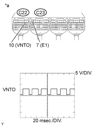
| 3.INSPECT ECM (VNTO VOLTAGE) |
While idling the engine, check the waveform of the ECM connectors using an oscilloscope.
- Standard Voltage:
Tester Connection
| Condition
| Specified Condition
|
C22-10 (VNTO) - C23-7 (E1)
| Idling
| Correct waveform is as shown
|
Text in Illustration*a
| Component with harness connected
(ECM)
|
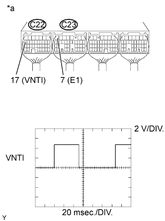
| 4.INSPECT ECM (VNTI VOLTAGE) |
While idling the engine, check the waveform of the ECM connectors using an oscilloscope.
- Standard Voltage:
Tester Connection
| Condition
| Specified Condition
|
C22-17 (VNTI) - C23-7 (E1)
| Idling
| Correct waveform is as shown
|
Text in Illustration*a
| Component with harness connected
(ECM)
|
| 5.REPAIR OR REPLACE HARNESS OR CONNECTOR |
Repair or replace the harness or connector.
Replace the ECM (HILUX_TGN26 RM0000013Z001IX.html).
| 7.REPLACE TURBO MOTOR DRIVER |
Replace turbo motor driver (HILUX_TGN26 RM000004QB2006X.html).
| 8.CONFIRM WHETHER MALFUNCTION HAS BEEN SUCCESSFULLY REPAIRED |
Connect the intelligent tester to the DLC3.
Turn the ignition switch to ON and turn the tester on.
Clear the DTCs (HILUX_TGN26 RM000000PDK12SX.html).
Turn the ignition switch off.
Remove the EFI fuse from the engine room relay block and junction block assembly for more than 1 minute.
Turn the ignition switch to ON and wait for 10 seconds or more.
Start the engine.
Drive the vehicle with a city driving pattern at least 10 minutes.
Enter the following menus: Powertrain / Engine and ECT / DTC.
Confirm that the DTC is not output again.