READ VALUE USING GTS (ACCELERATOR PEDAL POSITION SENSOR)
CHECK HARNESS AND CONNECTOR (ACCELERATOR PEDAL POSITION SENSOR - ECM)
REPLACE ACCELERATOR PEDAL SENSOR ASSEMBLY
CHECK WHETHER DTC OUTPUT RECURS (DTC P2121)
REPAIR OR REPLACE HARNESS OR CONNECTOR
CONFIRM WHETHER MALFUNCTION HAS BEEN SUCCESSFULLY REPAIRED
DTC P2121 Throttle / Pedal Position Sensor / Switch "D" Circuit Range / Performance |
DESCRIPTION
Refer to DTC P2120 (HILUX_TGN26 RM0000018WX076X.html).| DTC Detection Drive Pattern | DTC Detection Condition | Trouble Area |
Ignition switch ON
| The difference between VPA and VPA2 is less than 0.4 V, or more than 1.2 V for 0.5 seconds (1 trip detection logic). |
|
| DTC No. | Data List |
| P2121 |
|
WIRING DIAGRAM
Refer to DTC P2120 (HILUX_TGN26 RM0000018WX076X_02.html).INSPECTION PROCEDURE
- NOTICE:
- After replacing the ECM, the new ECM needs registration (HILUX_TGN26 RM0000012XK05AX.html) and initialization (HILUX_TGN26 RM000000TIN058X.html).
- HINT:
- Read freeze frame data using the GTS. Freeze frame data records the engine condition when malfunctions are detected. When troubleshooting, freeze frame data can help determine if the vehicle was moving or stationary, if the engine was warmed up or not, and other data from the time the malfunction occurred.
| 1.READ VALUE USING GTS (ACCELERATOR PEDAL POSITION SENSOR) |
Connect the GTS to the DLC3.
 |
Turn the ignition switch to ON and turn the GTS on.
Enter the following menus: Powertrain / Engine / Data List / Accel Sens. No.1 Volt % and Accel Sens. No.2 Volt %.
Read the values.
- Standard:
Accelerator Pedal Accel Sens. No.1 Volt % Accel Sens. No.2 Volt % Released 10 to 22% 24 to 40% Depressed 52 to 90% 68 to 99%
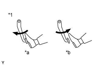
Text in Illustration *1 Accelerator Pedal Assembly *a Depressed *b Released Result Result Proceed to NG A OK B
|
| ||||
| A | |
| 2.CHECK HARNESS AND CONNECTOR (ACCELERATOR PEDAL POSITION SENSOR - ECM) |
Disconnect the accelerator pedal position sensor connector.
Disconnect the ECM connector.
Measure the resistance according to the value(s) in the table below.
- Standard Resistance:
Tester Connection Condition Specified Condition G6-1 (VCP2) - G156-4 (VCP2) Always Below 1 Ω G6-2 (EPA2) - G156-3 (EPA2) Always Below 1 Ω G6-3 (VPA2) - G157-1 (VPA2) Always Below 1 Ω G6-4 (VCPA) - G156-6 (VCPA) Always Below 1 Ω G6-5 (EPA) - G156-5 (EPA) Always Below 1 Ω G6-6 (VPA) - G157-2 (VPA) Always Below 1 Ω G6-1 (VCP2) or G156-4 (VCP2) - Body ground Always 10 kΩ or higher G6-3 (VPA2) or G157-1 (VPA2) - Body ground Always 10 kΩ or higher G6-4 (VCPA) or G156-6 (VCPA) - Body ground Always 10 kΩ or higher G6-6 (VPA) or G157-2 (VPA) - Body ground Always 10 kΩ or higher
Reconnect the accelerator pedal position sensor connector.
Reconnect the ECM connector.
|
| ||||
| OK | |
| 3.REPLACE ACCELERATOR PEDAL SENSOR ASSEMBLY |
Replace the accelerator pedal sensor assembly (HILUX_TGN26 RM0000013ZF013X.html).
| NEXT | |
| 4.CHECK WHETHER DTC OUTPUT RECURS (DTC P2121) |
Connect the GTS to the DLC3.
Clear the DTCs (HILUX_TGN26 RM000000PDK12TX.html).
Turn the ignition switch to ON.
Fully release the accelerator pedal for 3 seconds or more, then depress it partway for 3 seconds or more, and then fully depress it for 3 seconds or more.
Enter the following menus: Powertrain / Engine / Trouble Codes.
Read the DTCs.
Result Result Proceed to P2121 is output A No DTC is output B
|
| ||||
| A | |
| 5.REPLACE ECM |
Replace the ECM (HILUX_TGN26 RM0000013Z001IX.html).
|
| ||||
| 6.REPAIR OR REPLACE HARNESS OR CONNECTOR |
Repair or replace the harness or connector.
| NEXT | |
| 7.CONFIRM WHETHER MALFUNCTION HAS BEEN SUCCESSFULLY REPAIRED |
Connect the GTS to the DLC3.
Clear the DTCs (HILUX_TGN26 RM000000PDK12TX.html).
Turn the ignition switch off.
Turn the ignition switch to ON.
Fully release the accelerator pedal for 3 seconds or more, then depress it partway for 3 seconds or more, and then fully depress it for 3 seconds or more.
Enter the following menus: Powertrain / Engine / Trouble Codes.
Confirm that the DTC is not output again.
| NEXT | ||
| ||