READ VALUE USING GTS (VEHICLE SPEED)
CHECK COMBINATION METER SYSTEM
CHECK HARNESS AND CONNECTOR (COMBINATION METER ASSEMBLY - ECM)
CHECK HARNESS AND CONNECTOR (DRIVER SIDE JUNCTION BLOCK ASSEMBLY - ECM)
DTC P0500 Vehicle Speed Sensor "A" |
DESCRIPTION
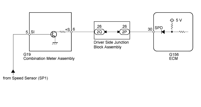
The vehicle speed sensor outputs a 4 pulse signal for every revolution of the rotor shaft, which is rotated by the transmission output shaft via the driven gear. After this signal is converted into a more precise rectangular waveform by the waveform shaping circuit inside the combination meter, it is then transmitted to the ECM. The ECM determines the vehicle speed based on the frequency of these pulse signals.
| DTC Detection Drive Pattern | DTC Detection Condition | Trouble Area |
| Drive the vehicle at 10 km/h (6.3 mph) or more | Conditions (a), (b) and (c) are met for 8 seconds or more (2 trip detection logic): (a) Engine coolant temperature is higher than 70°C (158°F). (b) Injection volume is 19 mm3/st or more. (c) No speed signal is input to the ECM. |
|
| Drive the vehicle at 10 km/h (6.3 mph) or more | Conditions (a) and (b) are met for 5 seconds or more (2 trip detection logic): (a) The fuel-cut operation is being performed. (b) No speed signal is input to the ECM. |
| DTC No. | Data List |
| P0500 | Vehicle Speed |
WIRING DIAGRAM
INSPECTION PROCEDURE
- NOTICE:
- Inspect the fuses of circuits related to this system before performing the following inspection procedure.
- After replacing the ECM, the new ECM needs registration (HILUX_TGN26 RM0000012XK05AX.html) and initialization (HILUX_TGN26 RM000000TIN058X.html).
- HINT:
- Read freeze frame data using the GTS. Freeze frame data records the engine condition when malfunctions are detected. When troubleshooting, freeze frame data can help determine if the vehicle was moving or stationary, if the engine was warmed up or not, and other data from the time the malfunction occurred.
| 1.READ VALUE USING GTS (VEHICLE SPEED) |
Connect the GTS to the DLC3.
Turn the ignition switch to ON.
Turn the GTS on.
Enter the following menus: Powertrain / Engine / Data List / Vehicle Speed.
Drive the vehicle.
Read the value displayed on the GTS.
- OK:
- Vehicle speeds displayed on GTS and speedometer display are equal.
|
| ||||
| NG | |
| 2.CHECK COMBINATION METER SYSTEM |
Inspect the circuits that send vehicle speed signals to this system in the combination meter system (HILUX_TGN26 RM000002UD7086X.html).
During inspection for the meter section, if there is an instruction that indicates to go back to inspections for each system, proceed to the next step.
| NEXT | |
| 3.CHECK HARNESS AND CONNECTOR (COMBINATION METER ASSEMBLY - ECM) |
Disconnect the combination meter assembly connector.
Disconnect the ECM connector.
Measure the resistance according the value(s) in the table below.
- Standard Resistance:
Tester Connection Condition Specified Condition G19-6 (+S) - G156-30 (SPD) Always Below 1 Ω
Reconnect the combination meter assembly connector.
Reconnect the ECM connector.
|
| ||||
| NG | |
| 4.CHECK HARNESS AND CONNECTOR (DRIVER SIDE JUNCTION BLOCK ASSEMBLY - ECM) |
Disconnect the driver side junction block assembly connector.
Disconnect the ECM connector.
Measure the resistance according the value(s) in the table below.
- Standard Resistance:
Tester Connection Condition Specified Condition 2P-26 - G156-30 (SPD) Always Below 1 Ω
Reconnect the driver side junction block assembly connector.
Reconnect the ECM connector.
|
| ||||
| OK | ||
| ||