DESCRIPTION
WIRING DIAGRAM
INSPECTION PROCEDURE
CHECK OTHER DTC OUTPUT (IN ADDITION TO DTC P2006)
CHECK AIR INTAKE SYSTEM
REPAIR OR REPLACE AIR INTAKE SYSTEM
CHECK INTAKE MANIFOLD (SWIRL CONTROL VALVE OPERATION)
READ VALUE USING INTELLIGENT TESTER (MAF AND MAP)
REPLACE MASS AIR FLOW METER
CHECK AND REPLACE TURBOCHARGER SUB-ASSEMBLY
CHECK CONNECTION OF VACUUM HOSE
PERFORM ACTIVE TEST USING INTELLIGENT TESTER (ACTIVATE THE VSV FOR SWIRL CONTROL VALVE)
INSPECT ELECTRIC EGR CONTROL VALVE ASSEMBLY
REPLACE ELECTRIC EGR CONTROL VALVE ASSEMBLY
INSPECT INTAKE MANIFOLD (SWIRL CONTROL VALVE OPERATION)
REPAIR OR REPLACE VACUUM HOSE
REPLACE INTAKE MANIFOLD
REPLACE VACUUM CONTROL VALVE SET
PERFORM ACTIVE TEST USING INTELLIGENT TESTER (ACTIVATE THE VSV FOR SWIRL CONTROL VALVE)
REPLACE ECM
CONFIRM WHETHER MALFUNCTION HAS BEEN SUCCESSFULLY REPAIRED
DTC P2006 Intake Manifold Runner Control Stuck Closed (Bank 1) |
DESCRIPTION
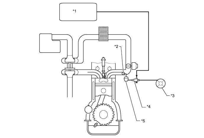
The swirl control valve is mounted on the intake manifold. The vacuum switching valve is used to change the vacuum to control the swirl control valve.The ECM determines the opening angle of the swirl control valve, and uses the vacuum switching valve (for swirl control valve) to change the vacuum applied to the actuator's diaphragm to open and close the swirl control valve.DTC Detection Drive Pattern
| DTC Detection Condition
| Trouble Area
|
After warming up engine, drive vehicle at an engine speed of 3200 rpm or more with high load for 1 minute or more.*
| When actual intake air volume detected by mass air flow meter continues to be smaller than volume estimated from boost pressure and intake air temperature sensor, ECM determines that swirl control valve is stuck closed (1 trip detection logic).
| - Vacuum switching valve (for swirl control valve)
- Open or short in vacuum switching valve (for swirl control valve) circuit
- Intake manifold (swirl control valve)
- Electric EGR control valve assembly
- Turbocharger sub-assembly
- Mass air flow meter
- Air cleaner hose
- Vacuum hose
- Air cleaner element is clogged
- Intake hose is disconnected
- ECM
|
- HINT:
- *: When the above driving pattern cannot be performed due to road conditions, etc., the swirl control valve can be determined to be functioning normally if mass air flow is 84 gm/s or more and MAP is 105 kPa or higher when the engine speed is at 4000 rpm with no load. However, no DTCs are stored when inspecting the vehicle with this method.
- The above values were measured under standard atmospheric pressure. The values are influenced by elevation, weather conditions, etc.
- Standard atmospheric pressure is 101 kPa. For every 100 m increase in elevation, pressure drops by 1 kPa. This varies by weather.
Text in Illustration*1
| ECM
| *2
| Swirl Control Valve
|
*3
| Vacuum Pump
| *4
| Vacuum Switching Valve (for Swirl Control Valve)
|
*5
| Swirl Control Valve Actuator
| -
| -
|
WIRING DIAGRAM
INSPECTION PROCEDURE
- NOTICE:
- Inspect the fuses of circuits related to this system before performing the following inspection procedure.
- After replacing the ECM, the new ECM needs registration (HILUX_TGN26 RM0000012XK07EX.html) and initialization (HILUX_TGN26 RM000000TIN056X.html).
- After replacing the fuel supply pump assembly, the ECM needs initialization (HILUX_TGN26 RM000000TIN056X.html).
- After replacing an injector assembly, the ECM needs registration (HILUX_TGN26 RM0000012XK07EX.html).
- HINT:
- Read freeze frame data using the intelligent tester. Freeze frame data records the engine condition when malfunctions are detected. When troubleshooting, freeze frame data can help determine if the vehicle was moving or stationary, if the engine was warmed up or not, and other data from the time the malfunction occurred.
| 1.CHECK OTHER DTC OUTPUT (IN ADDITION TO DTC P2006) |
Connect the intelligent tester to the DLC3.
Turn the ignition switch to ON and turn the tester on.
Enter the following menus: Powertrain / Engine and ECT / DTC.
Read the DTCs.
ResultResult
| Proceed to
|
P2006 is output
| A
|
P2006 and other DTCs are output
| B
|
- HINT:
- When MAP, mass air flow, Intake Air, and/or Intake Air Temp (Turbo)-related DTCs are stored along with P2006, perform troubleshooting for those DTCs first.
- MAP-related DTCs: P0107 and P0108 (HILUX_TGN26 RM00000187U087X.html).
- MAF-related DTCs: P0100 (HILUX_TGN26 RM00000187J06AX.html).
- Intake Air-related DTCs: P0112 and P0113 (HILUX_TGN26 RM00000187L065X.html).
- Intake Air Temp (Turbo)-related DTCs: P007C and P007D (HILUX_TGN26 RM00000188106FX.html).
| 2.CHECK AIR INTAKE SYSTEM |
Check for air leaks and blockages between the air cleaner case and turbocharger, and between the turbocharger and intake manifold.
ResultResult
| Proceed to
|
Leaks and/or blockages exist in the intake system
| A
|
No leaks or blockages in the intake system
| B
|
- HINT:
- Inspect the air intake system, especially hoses and pipes between the air cleaner and turbocharger.
- Check if the air cleaner element is significantly dirty.
- Check for abnormal disconnections, pipe and hose squashing, and any damage in the intake system.
- Using your hand, check whether the pipes and hoses in the intake system are securely connected.
- By applying soapy water and revving up the engine, air leaks from the intake system can be checked by checking for bubbles.
- Check for any modifications in the intake system made by the user.
| 3.REPAIR OR REPLACE AIR INTAKE SYSTEM |
Repair or replace the malfunctioning part in the air intake system.
| 4.CHECK INTAKE MANIFOLD (SWIRL CONTROL VALVE OPERATION) |
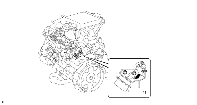
Check the movement of the swirl control valve immediately after starting the engine.
Text in Illustration*1
| Swirl Control Valve
| -
| -
|
- OK:
- Swirl control valve rod moves smoothly in the direction indicated by the arrow in the illustration.
| 5.READ VALUE USING INTELLIGENT TESTER (MAF AND MAP) |
Connect the intelligent tester to the DLC3.
Start the engine and turn the tester on.
Warm up the engine (engine coolant temperature is 70°C (158°F) or higher).
Enter the following menus: Powertrain / Engine and ECT / Data List / MAP and MAF.
Take a snapshot when the engine speed is maintained at 4000 rpm with no load.
Read the values of "MAP" and "MAF" in the Data List using the snapshot review function.
ResultResult
| Proceed to
|
MAF 84 gm/s or more and MAP 105 kPa or higher
| C
|
MAP below 90 kPa
| B
|
Except above
| A
|
- HINT:
- The shift lever should be in neutral and the A/C switch and all accessory switches should be off.
- The above values were measured under standard atmospheric pressure. The values are influenced by elevation, weather conditions, etc.
Standard atmospheric pressure is 101 kPa. For every 100 m increase in elevation, pressure drops by 1 kPa. This varies by weather.
| 6.REPLACE MASS AIR FLOW METER |
Replace the mass air flow meter (HILUX_TGN26 RM000000VHD04EX.html).
- HINT:
- If foreign matter is stuck inside the mass air flow meter, the output characteristics of the mass air flow meter may change, resulting in a malfunction.
| 7.CHECK AND REPLACE TURBOCHARGER SUB-ASSEMBLY |
Check the turbocharger sub-assembly (HILUX_TGN26 RM000003TBT00ZX.html).
Replace the turbocharger sub-assembly (HILUX_TGN26 RM000002S6F00NX.html).
- HINT:
- It is only necessary to replace the part when the results of the inspection indicate a problem.
| 8.CHECK CONNECTION OF VACUUM HOSE |
Check the connection of the swirl control valve system vacuum hose.
| 9.PERFORM ACTIVE TEST USING INTELLIGENT TESTER (ACTIVATE THE VSV FOR SWIRL CONTROL VALVE) |
Disconnect the vacuum hoses from the VSV for swirl control valve.
Connect the intelligent tester to the DLC3.
Turn the ignition switch to ON and turn the tester on.
Enter the following menus: Powertrain / Engine and ECT / Active Test / Activate the VSV for Swirl Control Valve.
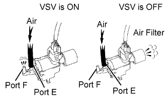
Check the VSV operation when it is operated using the intelligent tester.
- OK:
Tester Operation
| Specified Condition
|
VSV ON
| Air from port E flows out through port F
|
VSV OFF
| Air from port E flows out through air filter
|
Reconnect the vacuum hoses.
| 10.INSPECT ELECTRIC EGR CONTROL VALVE ASSEMBLY |
Inspect the electric EGR control valve assembly (HILUX_TGN26 RM000003TCI00IX.html).
- HINT:
- If there are any deposits adhering to the valve, clean the valve. When cleaning the valve, use diesel fuel or kerosene.
- When inspecting the electric EGR control valve assembly, make sure that the valve is fully closed.
| 11.REPLACE ELECTRIC EGR CONTROL VALVE ASSEMBLY |
Replace the electric EGR control valve assembly (HILUX_TGN26 RM000004QWK00HX.html).
| 12.INSPECT INTAKE MANIFOLD (SWIRL CONTROL VALVE OPERATION) |
Inspect the intake manifold (swirl control valve) (HILUX_TGN26 RM0000044GD009X.html).
- HINT:
- If there are any deposits adhering to the valve, clean the valve.
- If there are any deposits adhering to the valve, clean the valve. When cleaning the valve, use diesel fuel or kerosene.
- Apply vacuum to the diaphragm of the swirl control valve and check that the valve opens and closes smoothly.
| 13.REPAIR OR REPLACE VACUUM HOSE |
Repair or replace the vacuum hose.
| 14.REPLACE INTAKE MANIFOLD |
Replace the intake manifold (swirl control valve) (HILUX_TGN26 RM0000044GF00OX.html).
| 15.REPLACE VACUUM CONTROL VALVE SET |
Replace the vacuum control valve set (HILUX_TGN26 RM0000044GF00OX.html).
- HINT:
- Before replacing the vacuum control valve set, perform a wire harness inspection and if there are any problems with the wire harness, repair or replace it.
| 16.PERFORM ACTIVE TEST USING INTELLIGENT TESTER (ACTIVATE THE VSV FOR SWIRL CONTROL VALVE) |
Disconnect the vacuum hoses from the vacuum switching valve (for swirl control valve).
Connect the intelligent tester to the DLC3.
Turn the ignition switch to ON and turn the tester on.
Enter the following menus: Powertrain / Engine and ECT / Active Test / Activate the VSV for Swirl Control Valve.
Check the VSV operation when it is operated using the intelligent tester.
- OK:
Tester Operation
| Specified Condition
|
VSV ON
| Air from port E flows out through port F
|
VSV OFF
| Air from port E flows out through air filter
|
Reconnect the vacuum hoses.
Replace the ECM (HILUX_TGN26 RM0000013Z001IX.html).
| 18.CONFIRM WHETHER MALFUNCTION HAS BEEN SUCCESSFULLY REPAIRED |
Connect the intelligent tester to the DLC3.
Start the engine and turn the tester on.
Warm up the engine (engine coolant temperature is 70°C (158°F) or higher).
Enter the following menus: Powertrain / Engine and ECT / Data List / MAP and MAF.
Take a snapshot when the engine speed is maintained at 4000 rpm with no load.
Read the values of "MAP" and "MAF" in the Data List using the snapshot review function.
- OK:
- MAF is 84 gm/s or more and MAP is 105 kPa or higher.
- HINT:
- The shift lever should be in neutral and the A/C switch and all accessory switches should be off.
- The above values were measured under standard atmospheric pressure. The values are influenced by elevation, weather conditions, etc.
Standard atmospheric pressure is 101 kPa. For every 100 m increase in elevation, pressure drops by 1 kPa. This varies by weather.