Dtc P0230 Fuel Pump Primary Circuit
DESCRIPTION
WIRING DIAGRAM
INSPECTION PROCEDURE
INSPECT ECM (FPR VOLTAGE)
INSPECT RELAY (F-PMP/FFV)
CHECK HARNESS AND CONNECTOR (F-PMP/FFV RELAY - ECM, NO. 1 INTEGRATION RELAY)
DTC P0230 Fuel Pump Primary Circuit |
DESCRIPTION
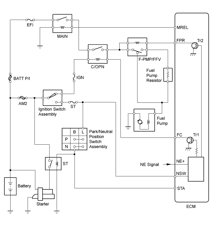
As shown in the illustration, when the engine is cranked, current flows from terminal ST1 of the ignition switch into the ECM and the ST relay coil.When the STA signal and NE signal are input to the ECM, Tr1 (power transistor 1) is turned ON, current flows to the coil of the C/OPN relay, the relay switches on, power is supplied to the fuel pump, and the fuel pump operates.While the NE signal is generated (engine running), the ECM keeps the Tr1 ON (C/OPN relay ON) and the fuel pump also keeps operating.The fuel pump speed is controlled at two levels (high speed or low speed) by engine condition (starting, light load, heavy load). When the engine starts (STA ON), Tr2 (power transistor 2) in the ECM is OFF, so the F-PMP/FFV relay closes and positive battery voltage is applied directly to the fuel pump. The fuel pump operates at high speed.During idling or under light loads, Tr2 goes ON, and then power is supplied to the fuel pump via the fuel pump resistor. The fuel pump operates at low speed.DTC No.
| DTC Detection Conditions
| Trouble Areas
|
P0230
| Open or short in F-PMP/FFV relay circuit
(1 trip detection logic)
| - Open or short in fuel pump relay circuit
- F-PMP/FFV relay
- ECM
|
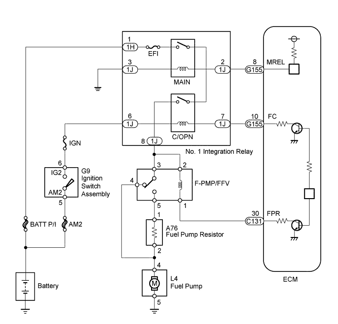
WIRING DIAGRAM
INSPECTION PROCEDURE
- HINT:
- This DTC chart is based on the premise that the engine is started normally. If the engine is difficult to start, proceed to the problem symptoms table (HILUX_TGN26 RM000000PDG0R6X.html).
- Read freeze frame data using an intelligent tester. Freeze frame data records the engine condition when malfunctions are detected. When troubleshooting, freeze frame data can help determine if the vehicle was moving or stationary, if the engine was warmed up or not, if the air fuel ratio was lean or rich, and other data from the time the malfunction occurred.
| 1.INSPECT ECM (FPR VOLTAGE) |
Measure the voltage according to the value(s) in the table below.
- Standard Voltage:
Tester Connection
| Condition
| Specified Condition
|
C131-30 (FPR) - Body ground
| STA signal ON
| 11 to 14 V
|
STA signal OFF (engine idling)
| Below 3 V
|
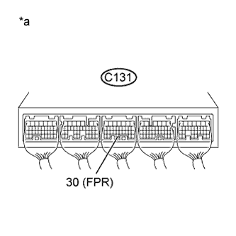
Text in Illustration*a
| Component with harness connected
(ECM)
|
| 2.INSPECT RELAY (F-PMP/FFV) |
Inspect the F-PMP/FFV relay (HILUX_TGN26 RM000003BLB02FX_01_0017.html).
| | REPLACE RELAY (F-PMP/FFV) |
|
|
| 3.CHECK HARNESS AND CONNECTOR (F-PMP/FFV RELAY - ECM, NO. 1 INTEGRATION RELAY) |
Remove the F-PMP/FFV relay from the engine room relay block and junction block assembly.
Remove the No. 1 integration relay from the engine room relay block and junction block assembly.
Disconnect the ECM connector.
Measure the resistance according to the value(s) in the table below.
- Standard Resistance:
Tester Connection
| Condition
| Specified Condition
|
F-PMP/FFV relay terminal 1 - C131-30 (FPR)
| Always
| Below 1 Ω
|
F-PMP/FFV relay terminal 2 - 1J-8
| Always
| Below 1 Ω
|
F-PMP/FFV relay terminal 1 or C131-30 (FPR) - Body ground
| Always
| 10 kΩ or higher
|
F-PMP/FFV relay terminal 2 or 1J-8 - Body ground
| Always
| 10 kΩ or higher
|
| | REPAIR OR REPLACE HARNESS OR CONNECTOR |
|
|