Meter / Gauge System (For Hatchback) Speedometer Malfunction
DESCRIPTION
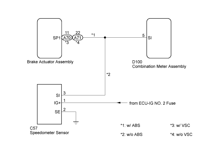
WIRING DIAGRAM
INSPECTION PROCEDURE
SYSTEM CHECK
READ VALUE USING TECHSTREAM (VEHICLE SPEED)
INSPECT COMBINATION METER ASSEMBLY (OUTPUT VOLTAGE)
INSPECT COMBINATION METER ASSEMBLY (INPUT WAVEFORM)
CHECK HARNESS AND CONNECTOR (BRAKE ACTUATOR ASSEMBLY - COMBINATION METER ASSEMBLY)
PERFORM ACTIVE TEST USING TECHSTREAM (SPEED METER OPERATION)
INSPECT SPEEDOMETER SENSOR
CHECK HARNESS AND CONNECTOR (SPEEDOMETER SENSOR - COMBINATION METER ASSEMBLY)
METER / GAUGE SYSTEM (for Hatchback) - Speedometer Malfunction |
DESCRIPTION
w/ ABS:
- The combination meter assembly controls the speedometer in accordance with vehicle speed signals from brake actuator assembly.
- HINT:
- Factors that affect the indicated vehicle speed include tire size, tire inflation, and tire wear. The speed indicated on the speedometer has an allowable margin of error. This can be tested using a speedometer tester (calibrated chassis dynamometer). For details about testing and the margin of error, see the reference chart (YARIS_NCP93 RM0000014WB073X_01_0001.html).
- If the vehicle speed sensor circuit has a malfunction, the brake actuator assembly stores the DTCs. Troubleshoot the Vehicle Stability Control System (for Hatchback with VSC/Built-in Type Yaw Rate Sensor) (YARIS_NCP93 RM000000XHV0CQX.html).
- If the vehicle speed sensor circuit has a malfunction, the brake actuator assembly stores the DTCs. Troubleshoot the Vehicle Stability Control System (for Hatchback with VSC/Separate Type Yaw Rate Sensor) (YARIS_NCP93 RM000000XHV0D3X.html).
- If the vehicle speed sensor circuit has a malfunction, the brake actuator assembly stores the DTCs. Troubleshoot the Anti-lock Brake System (for Hatchback without VSC) (YARIS_NCP93 RM000000XHV0CPX.html).
w/o ABS:
- The combination meter assembly controls the speedometer in accordance with vehicle speed signals from the speedometer sensor.
- HINT:
- Factors that affect the indicated vehicle speed include tire size, tire inflation, and tire wear. The speed indicated on the speedometer has an allowable margin of error. This can be tested using a speedometer tester (calibrated chassis dynamometer). For details about testing and the margin of error, see the reference chart (YARIS_NCP93 RM0000014WB073X_01_0001.html).
WIRING DIAGRAM
INSPECTION PROCEDURE
- CAUTION:
- If the vehicle speed is outside the allowable range when tested, perform the on-vehicle inspection (YARIS_NCP93 RM0000014WB073X_01_0001.html).
- HINT:
- Before starting the following inspection, check tire size and tire air pressure.
Check the vehicle specifications.
ResultResult
| Proceed to
|
w/ ABS
| A
|
w/o ABS
| B
|
| 2.READ VALUE USING TECHSTREAM (VEHICLE SPEED) |
Connect the Techstream to the DLC3.
Turn the ignition switch to ON.
Turn the Techstream on.
Enter the following menus: Chassis / ABS/VSC/TRC / Data List.
According to the display on the Techstream, read the Data List.
ABS/VSC/TRCTester Display
| Measurement Item/Range
| Normal Condition
| Diagnostic Note
|
Vehicle Speed
| Maximum wheel speed sensor reading
Min.: 0 km/h
Max.: 326 km/h
| Actual vehicle speed
| Speed indicated on speedometer
|
- OK:
- Vehicle speed displayed on the Techstream is approximately the same as the actual vehicle speed.
ResultResult
| Proceed to
|
OK
| A
|
NG (for Hatchback with VSC/Built-in Type Yaw Rate Sensor)
| B
|
NG (for Hatchback with VSC/Separate Type Yaw Rate Sensor)
| C
|
NG (for Hatchback without VSC)
| D
|
| 3.INSPECT COMBINATION METER ASSEMBLY (OUTPUT VOLTAGE) |
Disconnect the A70*1 or A71*2 brake actuator assembly connector.
Measure the voltage according to the value(s) in the table below.
- Standard Voltage:
Tester Connection
| Switch Condition
| Specified Condition
|
A70-11 (SP1)*1 - Body ground
A71-22 (SP1)*2 - Body ground
| Ignition switch ON
| 11 to 14 V
|
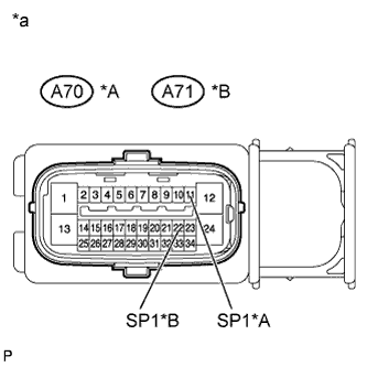
Text in Illustration*A
| w/ VSC
|
*B
| w/o VSC
|
*a
| Front view of wire harness connector
(to brake actuator assembly)
|
Reconnect the A70*1 or A71*2 brake actuator assembly connector.
- *1: w/ VSC
- *2: w/o VSC
| 4.INSPECT COMBINATION METER ASSEMBLY (INPUT WAVEFORM) |
Check the input waveform.
Remove the combination meter assembly with the connector(s) still connected.
Connect an oscilloscope to terminal D100-5 (SI) and body ground.
Turn the ignition switch to ON.
Turn the wheel slowly.
Check the signal waveform according to the condition(s) in the table below.
- Standard:
Item
| Condition
|
Tool setting
| 5 V/DIV., 20 ms./DIV.
|
Condition
| Driving at approx. 20 km/h
|
Text in Illustration*a
| Component with harness connected
(Combination Meter Assembly)
|
*b
| Waveform
|
- OK:
- The waveform is displayed as shown in the illustration.
- HINT:
- As the vehicle speed increases, the cycle of the waveform narrows.
| 5.CHECK HARNESS AND CONNECTOR (BRAKE ACTUATOR ASSEMBLY - COMBINATION METER ASSEMBLY) |
Disconnect the D100 combination meter assembly connector.
Disconnect the A70*1 or A71*2 brake actuator assembly connector.
Measure the resistance according to the value(s) in the table below.
- Standard Resistance:
Tester Connection
| Condition
| Specified Condition
|
D100-5 (SI) - A70-11 (SP1)*1
D100-5 (SI) - A71-22 (SP1)*2
| Always
| Below 1 Ω
|
D100-5 (SI) - Body ground
| Always
| 10 kΩ or higher
|
- *1: w/ VSC
- *2: w/o VSC
| | REPAIR OR REPLACE HARNESS OR CONNECTOR |
|
|
| 6.PERFORM ACTIVE TEST USING TECHSTREAM (SPEED METER OPERATION) |
Connect the Techstream to the DLC3.
Turn the ignition switch to ON.
Turn the Techstream on.
Enter the following menus: Body Electrical / Combination Meter / Active Test.
According to the display on the Techstream, perform the Active Test.
Combination MeterTester Display
| Test Part
| Control Range
| Diagnostic Note
|
Speed Meter Operation
| Speedometer
| 0, 40, 80, 120, 160, 200, 240 (km/h)
| Vehicle is stopped and the engine idling
|
- OK:
- Speedometer indication is normal.
| 7.INSPECT SPEEDOMETER SENSOR |
Remove the speedometer sensor.
Connect the positive (+) lead from the battery to terminal 1 and the negative(-) lead to terminal 2.
Connect the positive (+) lead from the tester to terminal 3 and the negative (-) lead to terminal 2.
Rotate the shaft.
Check that the voltage output between terminals 2 and 3 varies between 0 V and 11 V.
Text in Illustration*a
| Component without harness connected
(Speedometer Sensor)
|
Reinstall the speedometer sensor.
| | REPLACE SPEEDOMETER SENSOR |
|
|
| 8.CHECK HARNESS AND CONNECTOR (SPEEDOMETER SENSOR - COMBINATION METER ASSEMBLY) |
Disconnect the D100 combination meter assembly connector.
Disconnect the C57 speedometer sensor connector.
Measure the resistance according to the value(s) in the table below.
- Standard Resistance:
Tester Connection
| Condition
| Specified Condition
|
D100-5 (SI) - C57-3 (SI)
| Always
| Below 1 Ω
|
C57-2 (SE) - Body ground
| Always
| 10 kΩ or higher
|
Reconnect the D100 combination meter assembly connector.
Measure the voltage according to the value(s) in the table below.
- Standard Voltage:
Tester Connection
| Switch Condition
| Specified Condition
|
C57-1 (IG+) - Body ground
| Ignition switch ON
| 11 to 14 V
|
Reconnect the C57 speedometer sensor connector.
| | REPAIR OR REPLACE HARNESS OR CONNECTOR |
|
|