Lighting System (For Sedan) Acc Signal Circuit
DESCRIPTION
WIRING DIAGRAM
INSPECTION PROCEDURE
READ VALUE USING TECHSTREAM
PERFORM ACTIVE TEST USING TECHSTREAM
CHECK HARNESS AND CONNECTOR (ACC CUT RELAY - IGNITION SWITCH)
CHECK HARNESS AND CONNECTOR (ACC CUT RELAY - MAIN BODY ECU)
INSPECT ACC CUT RELAY
CHECK HARNESS AND CONNECTOR (ACC CUT RELAY - BATTERY)
CHECK HARNESS AND CONNECTOR (ACC CUT RELAY - ECM)
LIGHTING SYSTEM (for Sedan) - ACC Signal Circuit |
DESCRIPTION
This circuit detects the ignition switch ACC or off condition, and sends it to the main body ECU.
WIRING DIAGRAM
INSPECTION PROCEDURE
- NOTICE:
- Inspect the fuses for circuits related to this system before performing the following inspection procedure.
| 1.READ VALUE USING TECHSTREAM |
Connect the Techstream to the DLC3.
Turn the ignition switch to ON.
Turn the Techstream on.
Enter the following menus: Body Electrical / Main Body / Data List.
According to the display on the Techstream, read the Data List.
Main BodyTester Display
| Measurement Item/Range
| Normal Condition
| Diagnostic Note
|
ACC SW
| Ignition switch signal/
ON or OFF
| ON: Ignition switch ACC
OFF: Ignition switch off
| -
|
- OK:
- Normal conditions listed above are displayed.
| 2.PERFORM ACTIVE TEST USING TECHSTREAM |
Connect the Techstream to the DLC3.
Turn the ignition switch to ON.
Turn the Techstream on.
Enter the following menus: Powertrain / Engine and ECT / Active Test.
According to the display on the Techstream, perform the Active Test.
Engine and ECTTester Display
| Test Part
| Control Range
| Diagnostic Note
|
Activate the ACC CUT Relay
| ACC CUT relay
| ON or OFF
| Test possible when engine stopped
|
- OK:
- ACC CUT relay operating sound occurs.
| 3.CHECK HARNESS AND CONNECTOR (ACC CUT RELAY - IGNITION SWITCH) |
Remove the ACC CUT relay.
Measure the voltage according to the value(s) in the table below.
- Standard Voltage:
Tester Connection
| Switch Condition
| Specified Condition
|
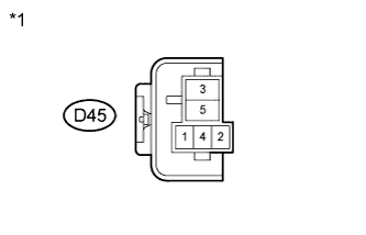
D45-3 - Body ground
| Ignition switch ON
| 11 to 14 V
|
Text in Illustration*1
| ACC CUT Relay Holder
|
| | REPAIR OR REPLACE HARNESS OR CONNECTOR |
|
|
| 4.CHECK HARNESS AND CONNECTOR (ACC CUT RELAY - MAIN BODY ECU) |
Remove the ACC CUT relay.
Disconnect the 4F main body ECU connector.
Measure the resistance according to the value(s) in the table below.
- Standard Resistance:
Tester Connection
| Condition
| Specified Condition
|
D45-4 - 4F-5
| Always
| Below 1 Ω
|
D45-4 - Body ground
| Always
| 10 kΩ or higher
|
| | REPAIR OR REPLACE HARNESS OR CONNECTOR |
|
|
Inspect the ACC CUT relay (YARIS_NCP93 RM000001E2C01HX.html).
| 6.CHECK HARNESS AND CONNECTOR (ACC CUT RELAY - BATTERY) |
Remove the ACC CUT relay.
Measure the voltage according to the value(s) in the table below.
- Standard Voltage:
Tester Connection
| Switch Condition
| Specified Condition
|
D45-2 - Body ground
| Always
| 11 to 14 V
|
Text in Illustration*1
| ACC CUT Relay Holder
|
| | REPAIR OR REPLACE HARNESS OR CONNECTOR |
|
|
| 7.CHECK HARNESS AND CONNECTOR (ACC CUT RELAY - ECM) |
Remove the ACC CUT relay.
Disconnect the A21 ECM connector.
Measure the resistance according to the value(s) in the table below.
- Standard Resistance:
Tester Connection
| Condition
| Specified Condition
|
D45-1 - A21-13 (ACCR)
| Always
| Below 1 Ω
|
D45-1 - Body ground
| Always
| 10 kΩ or higher
|
| | REPAIR OR REPLACE HARNESS OR CONNECTOR |
|
|