Power Steering System (For Hatchback) Ps Warning Light Remains On
DESCRIPTION
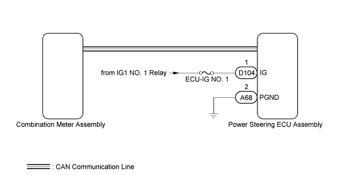
WIRING DIAGRAM
INSPECTION PROCEDURE
CHECK HARNESS AND CONNECTOR
CHECK CAN COMMUNICATION SYSTEM
CHECK HARNESS AND CONNECTOR (POWER STEERING ECU ASSEMBLY - BATTERY AND BODY GROUND)
REPLACE POWER STEERING ECU ASSEMBLY
PERFORM ASSIST MAP WRITING
CHECK EPS WARNING LIGHT
POWER STEERING SYSTEM (for Hatchback) - PS Warning Light Remains ON |
DESCRIPTION
If the power steering ECU assembly detects a malfunction, the EPS warning light comes on. At this time, the power steering ECU assembly stores a DTC in its memory.When the power supply voltage to the power steering ECU assembly (terminals IG) drops, required steering effort increases and the EPS warning light turns on.
WIRING DIAGRAM
INSPECTION PROCEDURE
- NOTICE:
- If the power steering ECU assembly is replaced, perform the torque sensor zero point calibration and assist map writing (YARIS_NCP93 RM000000OSZ018X.html).
- Inspect the fuses for circuits related to this system before performing the following inspection procedure.
- HINT:
- If the battery is not sufficiently charged or the voltage decreases temporarily, the amount of power assist may be reduced and the EPS warning light may come on. In such cases, the amount of power assist returns to normal when the battery voltage recovers. If the EPS warning light comes on but no DTCs are stored, check the Data List "Battery Voltage Lo Record" (YARIS_NCP93 RM000001AL8022X.html).
| 1.CHECK HARNESS AND CONNECTOR |
Turn the ignition switch to ON.
Check the indication condition of the EPS warning light by wiggling the power steering ECU assembly connector and wire harness up and down, and right and left.
- OK:
- EPS warning light indication condition does not change.
| | REPAIR OR REPLACE HARNESS OR CONNECTOR |
|
|
| 2.CHECK CAN COMMUNICATION SYSTEM |
Check for DTCs of the CAN communication system.
ResultResult
| Proceed to
|
DTCs is not output
| A
|
DTCs is output (for Hatchback except Separate Type Yaw Rate Sensor)
| B
|
DTCs is output (for Hatchback with Separate Type Yaw Rate Sensor)
| C
|
| 3.CHECK HARNESS AND CONNECTOR (POWER STEERING ECU ASSEMBLY - BATTERY AND BODY GROUND) |
Disconnect the power steering ECU assembly connectors.
Measure the voltage according to the value(s) in the table below.
- Standard Voltage:
Tester Connection
| Switch Condition
| Specified Condition
|
D104-1 (IG) - Body ground
| Ignition switch ON
| 11 to 14 V
|
Measure the resistance according to the value(s) in the table below.
- Standard Resistance:
Tester Connection
| Condition
| Specified Condition
|
A68-2 (PGND) - Body ground
| Always
| Below 1 Ω
|
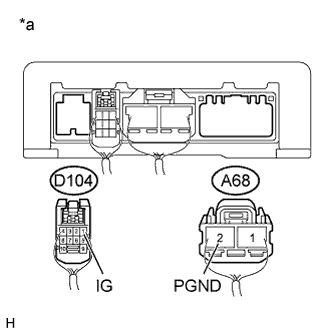
Text in Illustration*a
| Rear view of wire harness connector
(to Power Steering ECU Assembly)
|
| | REPAIR OR REPLACE HARNESS OR CONNECTOR |
|
|
| 4.REPLACE POWER STEERING ECU ASSEMBLY |
Replace the power steering ECU assembly (YARIS_NCP93 RM000002XN603ZX.html).
| 5.PERFORM ASSIST MAP WRITING |
Perform assist map writing (YARIS_NCP93 RM000000OSZ018X.html).
| 6.CHECK EPS WARNING LIGHT |
Check that the EPS warning light on the combination meter assembly does not come on.
- OK:
- The EPS warning light on the combination meter assembly does not come on.