Vehicle Stability Control System (For Sedan) -- Test Mode Procedure |
| TEST MODE PROCEDURE (SIGNAL CHECK) (When Using Techstream) |
- NOTICE:
- After replacement of the brake actuator assembly and/or yaw rate and acceleration sensor, perform zero point calibration of the yaw rate and acceleration sensor.
- HINT:
- If the ignition switch is turned from ON to ACC or off during Test Mode (signal check), DTCs recorded during the sensor check will be cleared.
- During Test Mode (signal check), the skid control ECU records all DTCs detected in the sensor check. By performing Test Mode (signal check), the codes are cleared if a normal condition is confirmed. The remaining codes are the codes indicating where an abnormality was found.
Procedure to enter Test Mode.
Turn the ignition switch off.
Check that the steering wheel is in the straight-ahead position.
for Automatic Transaxle model
Check that the shift lever is in P and apply the parking brake.
for Manual Transaxle model
Check that the shift lever is in N and apply the parking brake.Connect the Techstream to the DLC3.
Turn the ignition switch to ON.
Turn the Techstream on.
Switch the skid control ECU to Test Mode using the Techstream. Enter the following menus: Chassis / ABS/VSC/TRAC / Signal Check.
Check that the ABS warning and SLIP indicator lights come on for several seconds and then blink in the Test Mode.
- HINT:
- The TRAC OFF indicator light remains on during Test Mode because traction control is prohibited (The TRAC OFF indicator light goes off when the VSC OFF switch is ON).
- If the ABS warning and SLIP indicator lights do not blink, inspect the TS and CG terminal circuit and ABS warning and SLIP indicator light circuits
Trouble Area See procedure TS and CG terminal circuit YARIS_NCP93 RM000000XIU0DOX.html ABS warning light circuit (Remains on) YARIS_NCP93 RM000000XIH0BQX.html ABS warning light circuit (Does not come on) YARIS_NCP93 RM000000XIQ0BOX.html SLIP indicator light circuit (Remains on) YARIS_NCP93 RM000000YHI08JX.html SLIP indicator light circuit (Does not come on) YARIS_NCP93 RM000000YHJ08JX.html
| ACCELERATION SENSOR CHECK (When Using Techstream) |
Keep the vehicle stationary on a level surface for 1 second or more.
- HINT:
- The acceleration sensor check can be performed with the master cylinder pressure sensor check below.
| MASTER CYLINDER PRESSURE SENSOR CHECK (When Using Techstream) |
Leave the vehicle in a stationary condition and release the brake pedal for 1 second or more, and quickly and continuously depress the brake pedal with a force of 98 N (10 kgf, 22 lbf) or more for 1 second.
Check that the ABS warning light stays on for 3 seconds.
- HINT:
- Ensure that the ABS warning light comes on.
- While the ABS warning light stays on, continue to depress the brake pedal with a force of 98 N (10 kgf, 22 lbf) or more.
- The ABS warning light comes on for 3 seconds every time the brake pedal operation above is performed.
- If the master cylinder pressure sensor check is not completed, depressing the brake pedal causes further decreases in vacuum in the brake booster, making the sensor check difficult to complete.
- If the vacuum is insufficient, the master cylinder pressure sensor check may not be completed. In this case, run the engine at idle to obtain sufficient vacuum.
- If the brake pedal is strongly depressed when the vacuum is insufficient, the brake warning light may come on in accordance with booster pressure control. In this case, run the engine at idle to obtain sufficient vacuum.
| SPEED SENSOR CHECK (When Using Techstream) |
Check the speed sensor signal.
- NOTICE:
- Before performing the speed sensor signal check, complete the acceleration sensor and master cylinder pressure sensor checks.
Drive the vehicle straight-ahead.
Accelerate the vehicle to a speed of 45 km/h (28 mph) or more for several seconds and check that the ABS warning light goes off.- The sensor check may not be completed if wheelspin occurs.
- The ABS warning light blinks when the sensor check has been completed and the brake pedal is depressed.
- The ABS warning light comes on immediately after a malfunction has been detected during the speed sensor check.
- The sensor check may not be completed if wheelspin occurs.
Stop the vehicle.
- NOTICE:
- The speed sensor check may not be completed if the sensor check is started with the steering wheel turned or one or more wheels spinning.
- After the ABS warning light goes off and if the vehicle speed exceeds 80 km/h (50 mph), a sensor check code will be stored again. Decelerate or stop the vehicle before the speed reaches 80 km/h (50 mph).
- If the sensor check has not been completed, the ABS warning light blinks during driving and the ABS system does not operate.
- HINT:
- When the sensor check has been completed, the ABS warning light remains off during driving and blinks in the Test Mode pattern while the vehicle is stationary.
| YAW RATE SENSOR CHECK (When Using Techstream) |
Check the output of the yaw rate sensor.
Keep the vehicle in a stationary condition on a level surface for 1 second or more.
Move the shift lever from P to D (for automatic transaxle model) or release the parking brake (for manual transaxle model) and drive the vehicle at a speed of approximately 5 km/h (3 mph), and turn the steering wheel either to the left or right 90° or more until the vehicle makes a 180° turn.
for Automatic Transaxle model
Stop the vehicle, move the shift lever to P, and apply the parking brake. Check that the skid control buzzer sounds for 3 seconds.
for Manual Transaxle model
Stop the vehicle, move the shift lever to N, and apply the parking brake. Check that the skid control buzzer sounds for 3 seconds.- HINT:
- If the skid control buzzer sounds, the sensor check was completed normally.
- If the skid control buzzer does not sound, check the skid control buzzer circuit (YARIS_NCP93 RM000000XIS08FX.html), and then perform the sensor check again.
- If the skid control buzzer still does not sound, there is a malfunction in the yaw rate sensor, so check the DTC.
- Make a 180° turn. At the end of the turn, the direction of the vehicle should be 180° +/- 5° of its start position.
- Do not spin the wheels.
- Do not turn the ignition switch off while turning.
- Do not move the shift lever to P (for automatic transaxle model) or do not apply the parking brake (for manual transaxle model) while turning. Changing the vehicle speed, stopping, or driving in reverse is possible.
- Complete the turn within 20 seconds.
 |
| VSC OFF SWITCH CHECK |
Briefly press the VSC OFF switch.
Check that the TRAC OFF indicator light goes off.
Briefly press the VSC OFF switch again to turn the TRAC OFF indicator light on.
| END OF SENSOR CHECK (When Using Techstream) |
If the sensor check is completed, the ABS warning light blinks (Test Mode) when the vehicle stops and the ABS warning light is off while the vehicle is being driven.
- NOTICE:
- When the yaw rate sensor, acceleration sensor, speed sensor, and master cylinder pressure sensor checks are completed, the sensor check is completed.
- If the sensor check is not completed, the ABS warning light blinks even while the vehicle is being driven and the ABS does not operate.
| READ DTC OF SIGNAL CHECK FUNCTION (When Using Techstream) |
Read the DTC(s) by following the tester screen.
- NOTICE:
- If only the DTCs are displayed, repair the malfunction area and clear the DTCs.
- If Test Mode sensor check DTCs and other DTCs are displayed or if only Test Mode sensor check DTCs are displayed, repair the malfunctions, clear the DTCs, and perform the Test Mode inspection again.
List of DTCs.
ABS Sensor DTC Code Detection Item Trouble Area C1271 Low output signal from front speed sensor RH - Front speed sensor RH
- Sensor installation
- Speed sensor rotor
C1272 Low output signal from front speed sensor LH - Front speed sensor LH
- Sensor installation
- Speed sensor rotor
C1273 Low output signal from rear speed sensor RH - Rear speed sensor RH
- Sensor installation
- Speed sensor rotor
C1274 Low output signal from rear speed sensor LH - Rear speed sensor LH
- Sensor installation
- Speed sensor rotor
C1275 Abnormal change in output signal from front speed sensor RH Speed sensor rotor C1276 Abnormal change in output signal from front speed sensor LH Speed sensor rotor C1277 Abnormal change in output signal from rear speed sensor RH Speed sensor rotor C1278 Abnormal change in output signal from rear speed sensor LH Speed sensor rotor C1279 Acceleration sensor output voltage malfunction - Yaw rate and acceleration sensor
- Sensor installation
C1281 Master cylinder pressure sensor output malfunction - Stop light switch
- Master cylinder pressure sensor
VSC Sensor DTC Code Detection Item Trouble Area C0371 Yaw rate sensor Yaw rate and acceleration sensor - HINT:
- The codes in this table are output only in Test Mode (signal check).
- Front speed sensor RH
Turn the ignition switch off and disconnect the Techstream.
| TEST MODE PROCEDURE (SIGNAL CHECK) (When Using SST Check Wire) |
- NOTICE:
- After replacement of the brake actuator assembly and/or yaw rate and acceleration sensor, perform zero point calibration of the yaw rate and acceleration sensor.
- HINT:
- If the ignition switch is turned from ON to ACC or off during Test Mode (signal check), DTCs recorded during the sensor check will be cleared.
- During Test Mode (signal check), the skid control ECU records all DTCs detected in the sensor check. By performing Test Mode (signal check), the codes are cleared if a normal condition is confirmed. The remaining codes are the codes indicating where an abnormality was found.
Procedure to enter Test Mode.
Turn the ignition switch off.
Check that the steering wheel is in the straight-ahead position.
for Automatic Transaxle model
Check that the shift lever is in P and apply the parking brake.
for Manual Transaxle model
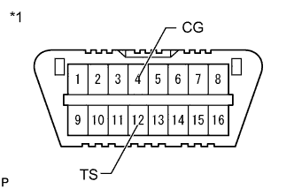
Check that the shift lever is in N and apply the parking brake.Using SST, connect terminals 12 (TS) and 4 (CG) of the DLC3.
Text in Illustration *1 Front view of DLC3 - SST
- 09843-18040
Turn the ignition switch to ON.
Check that the ABS warning and SLIP indicator lights come on for several seconds and then blink in the Test Mode.
- HINT:
- The TRAC OFF indicator light remains on during Test Mode because traction control is prohibited (The TRAC OFF indicator light goes off when the VSC OFF switch is ON).
- If the ABS warning and SLIP indicator lights do not blink, inspect the TS and CG terminal circuit and ABS warning and SLIP indicator light circuits.
Trouble Area See procedure TS and CG terminal circuit YARIS_NCP93 RM000000XIU0DOX.html ABS warning light circuit (Remains on) YARIS_NCP93 RM000000XIH0BQX.html ABS warning light circuit (Does not come on) YARIS_NCP93 RM000000XIQ0BOX.html SLIP indicator light circuit (Remains on) YARIS_NCP93 RM000000YHI08JX.html SLIP indicator light circuit (Does not come on) YARIS_NCP93 RM000000YHJ08JX.html
| ACCELERATION SENSOR CHECK (When Using SST Check Wire) |
Keep the vehicle stationary on a level surface for 1 second or more.
- HINT:
- The acceleration sensor check can be performed with the master cylinder pressure sensor check below.
| MASTER CYLINDER PRESSURE SENSOR CHECK (When Using SST Check Wire) |
Leave the vehicle in a stationary condition and release the brake pedal for 1 second or more, and quickly and continuously depress the brake pedal with a force of 98 N (10 kgf, 22 lbf) or more for 1 second.
Check that the ABS warning light stays on for 3 seconds.
- HINT:
- Ensure that the ABS warning light comes on.
- While the ABS warning light stays on, continue to depress the brake pedal with a force of 98 N (10 kgf, 22 lbf) or more.
- The ABS warning light comes on for 3 seconds every time the brake pedal operation above is performed.
- If the master cylinder pressure sensor check is not completed, depressing the brake pedal causes further decreases in vacuum in the brake booster, making the sensor check difficult to complete.
- If the vacuum is insufficient, the master cylinder pressure sensor check may not be completed. In this case, run the engine at idle to obtain sufficient vacuum.
- If the brake pedal is strongly depressed when the vacuum is insufficient, the brake warning light may come on in accordance with booster pressure control. In this case, run the engine at idle to obtain sufficient vacuum.
| SPEED SENSOR CHECK (When Using SST Check Wire) |
Check the speed sensor signal.
- NOTICE:
- Before performing the speed sensor signal check, complete the acceleration sensor and master cylinder pressure sensor signal checks.
Drive the vehicle straight-ahead.
Accelerate the vehicle to a speed of 45 km/h (28 mph) or more for several seconds and check that the ABS warning light goes off.- The sensor check may not be completed if wheelspin occurs.
- The ABS warning light blinks when the sensor check has been completed and the brake pedal is depressed.
- The ABS warning light comes on immediately after a malfunction has been detected during the speed sensor check.
- The sensor check may not be completed if wheelspin occurs.
Stop the vehicle.
- NOTICE:
- The speed sensor check may not be completed if the sensor check is started with the steering wheel turned or one or more wheels spinning.
- After the ABS warning light goes off and if the vehicle speed exceeds 80 km/h (50 mph), a sensor check code will be stored again. Decelerate or stop the vehicle before the speed reaches 80 km/h (50 mph).
- If the sensor check has not been completed, the ABS warning light blinks during driving and the ABS system does not operate.
- HINT:
- When the sensor check has been completed, the ABS warning light remains on during driving and blinks in the Test Mode pattern while the vehicle is stationary.
| YAW RATE SENSOR CHECK (When Using SST Check Wire) |
Check the output of the yaw rate sensor.
Keep the vehicle stationary on a level surface for 1 second or more.
Move the shift lever from P to D (for automatic transaxle model) or release the parking brake (for manual transaxle model) and drive the vehicle at a vehicle speed of approximately 5 km/h (3 mph) and turn the steering wheel either to the left or right 90° or more and until the vehicle makes a 180° turn.
for Automatic Transaxle model
Stop the vehicle, move the shift lever to P, and apply the parking brake. Check that the skid control buzzer sounds for 3 seconds.
for Manual Transaxle model
Stop the vehicle, move the shift lever to N, and apply the parking brake. Check that the skid control buzzer sounds for 3 seconds.- HINT:
- If the skid control buzzer sounds, the sensor check was completed normally.
- If the skid control buzzer does not sound, check the skid control buzzer circuit (YARIS_NCP93 RM000000XIS08FX.html), and then perform the sensor check again.
- If the skid control buzzer still does not sound, there is a malfunction in the yaw rate sensor, so check the DTC.
- Make a 180° turn. At the end of the turn, the direction of the vehicle should be 180° +/- 5° of its start position.
- Do not allow the wheels to spin.
- Do not turn the ignition switch off while turning.
- Do not move the shift lever to P (for automatic transaxle model) or do not apply the parking brake (for manual transaxle model) while turning. Changing the vehicle speed, stopping, or driving in reverse is possible.
- Complete the turn within 20 seconds.
|
| VSC OFF SWITCH CHECK |
Briefly press the VSC OFF switch.
Check that the TRAC OFF indicator light goes off.
Briefly press the VSC OFF switch again to turn the TRAC OFF indicator light on.
| END OF SENSOR CHECK (When Using SST Check Wire) |
If the sensor check is completed, the ABS warning light blinks (Test Mode) when the vehicle stops and the ABS warning light is off while the vehicle is being driven.
- NOTICE:
- When the yaw rate sensor, acceleration sensor, speed sensor, and master cylinder pressure sensor checks are completed, the sensor check is completed.
- If the sensor check is not completed, the ABS warning light will blink even while the vehicle is driven and the ABS will not operate.
| READ DTC OF SIGNAL CHECK FUNCTION (When Using SST Check Wire) |
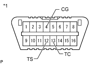
Using SST, connect terminals 12 (TS), 13 (TC) and 4 (CG) of the DLC3.
Text in Illustration *1 Front view of DLC3 - SST
- 09843-18040
Count the number of blinks of the ABS warning and SLIP indicator lights.
- HINT:
- When the system is operating correctly, each light will blink continuously in a pattern of 0.25 seconds on, then 0.25 seconds off.
- When one DTC is output, each lamp will output the same code at 4 second intervals. (For example, Code 21 would be output as 2 flashes, a 1.5 second pause, and then 1 flash)
- When 2 or more DTCs are output, each lamp will output a different code at 2.5 second intervals, and when all codes have been output, there will be a 4-second pause and the sequence will repeat.
- When multiple codes are set, they are output in order starting with the lowest DTC number.
- See the list of DTCs (See procedure "A").
- NOTICE:
- If only DTCs other than Test Mode sensor check DTCs are displayed, repair the malfunctions and clear the DTCs.
- If Test Mode sensor check DTCs and other DTCs are displayed or if only Test Mode sensor check DTCs are displayed, repair the malfunctions, clear the DTCs, and perform the Test Mode inspection again.
After performing the check, disconnect SST from terminals TS and CG, and TC and CG of the DLC3 and turn the ignition switch off.
Turn the ignition switch to ON.
- HINT:
- If the ignition switch is not turned to ON after SST is removed from the DLC3, the previous Test Mode will continue.
- If the ignition switch is turned to ON with terminals TS and CG shorted, the previous Test Mode will continue.
 |
| DTC OF TEST MODE (SIGNAL CHECK) FUNCTION (Procedure "A") |
| DTC Code | Detection Item | Trouble Area |
| 71 | Low output signal from front speed sensor RH |
|
| 72 | Low output signal from front speed sensor LH |
|
| 73 | Low output signal from rear speed sensor RH |
|
| 74 | Low output signal from rear speed sensor LH |
|
| 75 | Abnormal change in output signal from front speed sensor RH | Speed sensor rotor |
| 76 | Abnormal change in output signal from front speed sensor LH | Speed sensor rotor |
| 77 | Abnormal change in output signal from rear speed sensor RH | Speed sensor rotor |
| 78 | Abnormal change in output signal from rear speed sensor LH | Speed sensor rotor |
| 79 | Acceleration sensor output voltage malfunction |
|
| 81 | Master cylinder pressure sensor output malfunction |
|
| DTC Code | Detection Item | Trouble Area |
| 71 | Yaw rate sensor | Yaw rate and acceleration sensor |
- HINT:
- The codes in this table are output only in Test Mode (signal check).