Fuel Tank (For Hatchback) -- Installation |
| 1. INSTALL BREATHER TUBE CLAMP |
Engage the claw and pipe clamp and install the breather tube clamp.
| 2. INSTALL FUEL TANK FILLER PIPE PROTECTOR |
Engage the 2 claws and install the fuel tank filler pipe protector.
Engage the 2 claws and install the No. 2 fuel tube support protector.
Install the clip to the fuel tank filler pipe protector.
| 3. INSTALL FUEL TANK VENT HOSE |
Install the fuel tank vent hose sub-assembly onto the fuel tank assembly.
| 4. INSTALL FUEL TANK MAIN TUBE SUB-ASSEMBLY |
Install the fuel tank main tube onto the fuel tank assembly.
| 5. INSTALL FUEL TANK ASSEMBLY |
Clean and degrease the bolt holes.
Using an engine lifter, set the fuel tank assembly in the installation position.
Install the fuel tank assembly with new 4 bolts.
- Torque:
- 14 N*m{146 kgf*cm, 11 ft.*lbf}
Install the parking brake cable with the bolt.
- Torque:
- 6.0 N*m{61 kgf*cm, 53 in.*lbf}
Engage the claw and install the fuel tank filler pipe.
Install the bolt.
- Torque:
- 34 N*m{347 kgf*cm, 25 ft.*lbf}
| 6. CONNECT FUEL TANK VENT HOSE |
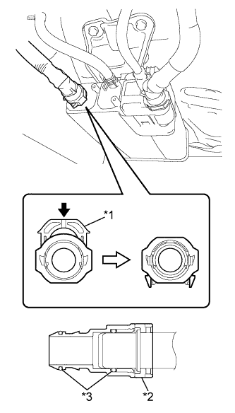
Connect the fuel tank vent hose and lock it by pushing in the retainer.
Text in Illustration *1 Retainer *2 Fuel Tank Vent Hose Connector *3 O-ring 
Push - NOTICE:
- Check that there are no scratches or foreign objects on the connecting part.
- Check that the fuel tank vent hose is inserted securely.
- After installing the retainer, check that the fuel tank vent hose is securely connected by pulling on it.
- HINT:
- Insert the inlet tube until a "click" sound is heard.
- The quick connector cannot be locked when the tube is not inserted securely.
 |
| 7. CONNECT FUEL TANK MAIN TUBE SUB-ASSEMBLY |
Connect the fuel tank main tube sub-assembly and lock it by pushing in the retainer.
- NOTICE:
- Check that there are no scratches or foreign objects on the connecting part.
- Check that the fuel tank main tube is inserted securely.
- After installing the checker, check that the fuel tank main tube is securely connected by pulling on it.
After connecting the fuel tube connector, pull on the fuel tube connector and the pipe to make sure they are firmly connected.
| 8. INSTALL FUEL TANK COVER VENT CASE SUB-ASSEMBLY |
Install the fuel tank cover vent case sub-assembly with the bolt and clip.
- Torque:
- 5.4 N*m{55 kgf*cm, 48 in.*lbf}
| 9. INSTALL FRONT NO. 4 FLOOR HEAT INSULATOR |
Install the front No. 4 floor heat insulator with the 2 nuts.
- Torque:
- 5.4 N*m{55 kgf*cm, 48 in.*lbf}
| 10. INSTALL EXHAUST PIPE GASKET |
Using a plastic hammer and a wooden block, tap in a new exhaust pipe gasket until its surface is flush with the exhaust manifold.
Text in Illustration *1 Exhaust Pipe Gasket *2 Wooden Block *3 Plastic Hammer *4 Exhaust Manifold - NOTICE:
- Install the gasket in the correct direction.
- Do not reuse the gasket.
- Do not damage the gasket by dropping it, etc.
- Do not damage the outer surface of the gasket.
- Do not push in the gasket with the exhaust pipe when connecting it.
 |
| 11. INSTALL NO. 2 EXHAUST PIPE GASKET |
Using a plastic hammer and a wooden block, tap in a new No. 2 exhaust pipe gasket until its surface is flush with the front exhaust pipe assembly.
Text in Illustration *1 No. 2 Exhaust Pipe Gasket *2 Wooden Block *3 Plastic Hammer *4 Front Exhaust Pipe Assembly - NOTICE:
- Install the gasket in the correct direction.
- Do not reuse the gasket.
- Do not damage the gasket by dropping it, etc.
- Do not damage the outer surface of the gasket.
- Do not push in the gasket with the exhaust pipe when connecting it.
|
| 12. INSTALL FRONT EXHAUST PIPE ASSEMBLY |
Using a vernier caliper, measure the free length of the compression spring.
- Minimum Length:
- 41.5 mm (1.634 in.)
- HINT:
- If the length is not as specified, replace the compression spring.
 |
Hang the front exhaust pipe assembly with the 3 exhaust pipe supports.
Install the front exhaust pipe assembly onto the exhaust manifold with the 2 compression springs and 2 bolts.
Text in Illustration *1 Exhaust Manifold *2 Front Exhaust Pipe Assembly *3 Exhaust Pipe Gasket *a Space between flanges: 8.5 mm (0.335 in.) - Torque:
- 43 N*m{438 kgf*cm, 32 ft.*lbf}
- HINT:
- After the installation, check that the gaps between the flanges of the exhaust manifold and front exhaust pipe assembly are consistent front-to-rear and left-to-right.
 |
Using a vernier caliper, measure the free length of the compression spring.
- Minimum Length:
- 38.5 mm (1.516 in.)
- HINT:
- If the length is not as specified, replace the compression spring.
|
Connect the tail exhaust pipe assembly to the front exhaust pipe assembly with the 2 compression springs and 2 bolts.
Text in Illustration *1 Front Exhaust Pipe Assembly *2 Tail Exhaust Pipe Assembly *3 No. 2 Exhaust Pipe Gasket *a Space between flanges: 6.5 mm (0.256 in.) - Torque:
- 43 N*m{438 kgf*cm, 32 ft.*lbf}
- HINT:
- After the installation, check that the gaps between the flanges of the front exhaust pipe assembly and tail exhaust pipe assembly are consistent front-to-rear and left-to-right.
 |
Pass the connector through the hole into the inside of the vehicle and install the oxygen sensor wire grommet.
Connect the oxygen sensor connector.
| 13. INSTALL FRONT FLOOR CENTER BRACE |
Install the front floor center brace onto the body with the 2 bolts.
- Torque:
- 30 N*m{307 kgf*cm, 22 ft.*lbf}
| 14. INSTALL REAR CONSOLE BOX ASSEMBLY |
| 15. ADD FUEL |
| 16. INSTALL FUEL SUCTION TUBE ASSEMBLY WITH PUMP AND GAUGE |