DESCRIPTION
WIRING DIAGRAM
INSPECTION PROCEDURE
READ VALUE USING TECHSTREAM (STARTER SIGNAL)
INSPECT ECM (STSW VOLTAGE)
INSPECT ECM (STAR VOLTAGE)
INSPECT PARK/NEUTRAL POSITION SWITCH
CHECK HARNESS AND CONNECTOR (PARK/NEUTRAL POSITION SWITCH - ECM)
INSPECT ECM (STAR VOLTAGE)
INSPECT CLUTCH START SWITCH
CHECK HARNESS AND CONNECTOR (CLUTCH START SWITCH - ECM)
INSPECT IGNITION SWITCH
CHECK HARNESS AND CONNECTOR (IGNITION SWITCH - PARK/NEUTRAL POSITION SWITCH - ECM)
CHECK HARNESS AND CONNECTOR (IGNITION SWITCH - CLUTCH START SWITCH - ECM)
INSPECT BATTERY
CHECK BATTERY TERMINAL
CHECK HARNESS AND CONNECTOR (PNP SWITCH OR CLUTCH START SWITCH - ST RELAY)
SFI SYSTEM (for Sedan) - Cranking Holding Function Circuit |
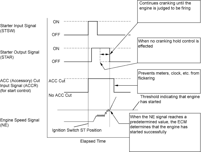
DESCRIPTION
The cranking holding control system provides a current to the starter when the ECM detects the ignition switch's start signal (STSW). When the ECM judges that the engine has started, the system cuts the current to the starter. When the ECM receives the STSW signal, it turns on the ACC (Accessory) relay, which prevents flickering of the combination meter, clock and audio system. Also, the ECM sends a signal to the ECM's STAR terminal. Then the STAR output signal travels through the Park/Neutral Position (PNP) switch to the ST relay, causing the starter to activate. When the engine is cranking, the starter operation signal is sent to the ECM's STA terminal.
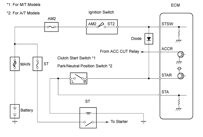
WIRING DIAGRAM
INSPECTION PROCEDURE
| 1.READ VALUE USING TECHSTREAM (STARTER SIGNAL) |
Connect the Techstream to the DLC3.
Turn the ignition switch to ON and turn the Techstream on.
Turn the Techstream on.
Enter the following menus: Powertrain / Engine and ECT / Engine and ECT / Starter Signal.
Check the result when the ignition switch is turned to ON and START.
- OK:
Ignition Switch Position
| Starter Signal
|
ON
| Close (Starter signal OFF)
|
START
| Open (Starter signal ON)
|
ResultResult
| Proceed to
|
NG
| A
|
OK
| B
|
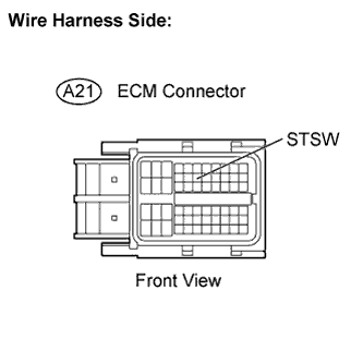
| 2.INSPECT ECM (STSW VOLTAGE) |
Disconnect the A21 ECM connector.
Measure the voltage between the terminals of the ECM connector and body ground while cranking the engine.
- Standard voltage:
Tester Connections
| Specified Conditions
|
STSW (A21-14) - Body ground
| 11 to 14 V
|
- Result:
Result
| Proceed to
|
Within standard range(A/T)
| A
|
Within standard range (M/T)
| B
|
Outside standard range
| C
|
Reconnect the ECM connector.
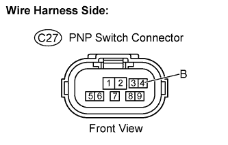
| 3.INSPECT ECM (STAR VOLTAGE) |
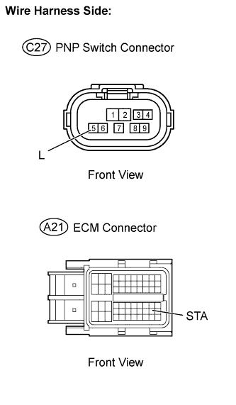
Disconnect the C27 Park/Neutral Position (PNP) switch connector.
Measure the voltage between the terminals of the PNP switch connector and body ground while cranking the engine.
- Standard voltage:
Tester Connections
| Specified Conditions
|
B (C27-4) - Body ground
| 11 to 14 V
|
Reconnect the PNP switch connector.
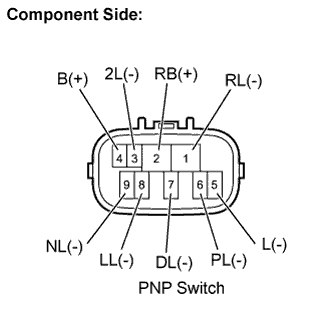
| 4.INSPECT PARK/NEUTRAL POSITION SWITCH |
Disconnect the C27 PNP switch connector.
Check the resistance between each terminal shown below when the shift lever is moved to each range.
- Standard resistance:
Tester Connections
| Shift Position
| Specified Conditions
|
PL (6) - RB (2)
| P
| Below 1 Ω
|
L (5) - B (4)
|
RL (1) - RB (2)
| R
|
NL (9) - RB (2)
| N
|
L (5) - B (4)
|
DL (7) - RB (2)
| D
|
2L (3) - RB (2)
| 2
|
LL (8) - RB (2)
| L
|
Reconnect the PNP switch connector.
| 5.CHECK HARNESS AND CONNECTOR (PARK/NEUTRAL POSITION SWITCH - ECM) |
Disconnect the C27 PNP switch connector.
Disconnect the A21 ECM connector.
Check the resistance.
- Standard resistance (Check for open):
Tester Connections
| Specified Conditions
|
L (C27-5) - STA (A21-48)
| Below 1 Ω
|
- Standard resistance (Check for short):
Tester Connections
| Specified Conditions
|
L (C27-5) or STA (A21-48) - Body ground
| 10 kΩ or higher
|
Reconnect the PNP switch connector.
Reconnect the ECM connector.
| | REPAIR OR REPLACE HARNESS OR CONNECTOR |
|
|
| 6.INSPECT ECM (STAR VOLTAGE) |
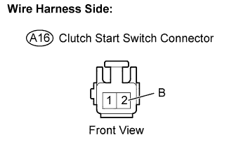
Disconnect the A16 clutch start switch connector.
Measure the voltage between the terminals of the clutch start switch connector and body ground while cranking the engine.
- Standard voltage:
Tester Connections
| Specified Conditions
|
B (A16-2) - Body ground
| 11 to 14 V
|
Reconnect the clutch start switch connector.
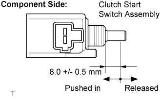
| 7.INSPECT CLUTCH START SWITCH |
Disconnect the A16 clutch start switch connector.
Check the resistance between the terminals of the clutch start switch.
- Standard resistance:
Switch Positions
| Specified Conditions
|
Pushed in
| Below 1 Ω
|
Released
| 10 kΩ or higher
|
Reconnect the clutch start switch connector.
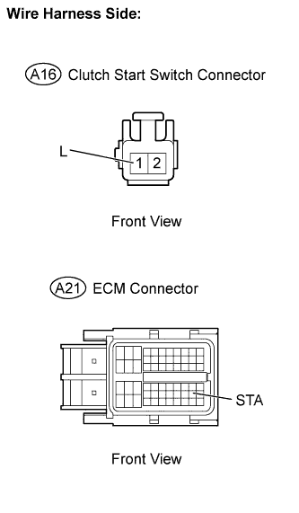
| 8.CHECK HARNESS AND CONNECTOR (CLUTCH START SWITCH - ECM) |
Disconnect the A16 clutch start switch connector.
Disconnect the A21 ECM connector.
Check the resistance.
- Standard resistance (Check for open):
Tester Connections
| Specified Conditions
|
L (A16-1) - STA (A21-48)
| Below 1 Ω
|
- Standard resistance (Check for short):
Tester Connections
| Specified Conditions
|
L (A16-1) or STA (A21-48) - Body ground
| 10 kΩ or higher
|
Reconnect the clutch start switch connector.
Reconnect the ECM connector.
| | REPAIR OR REPLACE HARNESS OR CONNECTOR |
|
|
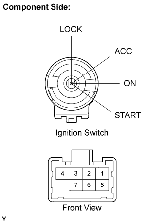
| 9.INSPECT IGNITION SWITCH |
Disconnect the D8 ignition switch connector.
Check the resistance between the terminals shown below.
- Standard resistance:
Key Positions
| Tester Connections
| Specified Conditions
|
LOCK
| -
| 10 kΩ or higher
|
ACC
| 2 - 4
| Below 1 Ω
|
ON
| 1 - 2 - 4
|
5 - 6
|
START
| 1 - 3 - 4
|
5 - 6 - 7
|
Reconnect the ignition switch connector.
| OK |
|
|
|
| REPAIR OR REPLACE HARNESS OR CONNECTOR (ECM - IGNITION SWITCH - BATTERY) |
|
| 10.CHECK HARNESS AND CONNECTOR (IGNITION SWITCH - PARK/NEUTRAL POSITION SWITCH - ECM) |
Disconnect the D8 ignition switch connector.
Disconnect the C27 PNP switch connector.
Disconnect the C20 ECM connector.
Check the resistance.
- Standard resistance (Check for open):
Tester Connections
| Specified Conditions
|
ST2 (D8-7) - B (C27-4)
| Below 1 Ω
|
STAR (C20-52) - B (C27-4)
|
STAR (C20-52) - L (C27-5)
|
- Standard resistance (Check for short):
Tester Connections
| Specified Conditions
|
ST2 (D8-7) or B (C27-4) - Body ground
| 10 kΩ or higher
|
STAR (C20-52) or B (C27-4) - Body ground
|
STAR (C20-52) or L (C27-5) - Body ground
|
Reconnect the ignition switch connector.
Reconnect the PNP switch connector.
Reconnect the ECM connector.
| | REPAIR OR REPLACE HARNESS OR CONNECTOR |
|
|
| 11.CHECK HARNESS AND CONNECTOR (IGNITION SWITCH - CLUTCH START SWITCH - ECM) |
Disconnect the D8 ignition switch connector.
Disconnect the A16 clutch start switch connector.
Disconnect the C20 ECM connector.
Check the resistance.
- Standard resistance (Check for open):
Tester Connections
| Specified Conditions
|
ST2 (D8-7) - B (A16-2)
| Below 1 Ω
|
STAR (C20-52) - B (A16-2)
|
STAR (C20-52) - L (A16-1)
|
- Standard resistance (Check for short):
Tester Connections
| Specified Conditions
|
ST2 (D8-7) or B (A16-2) - Body ground
| 10 kΩ or higher
|
STAR (C20-52) or B (A16-2) - Body ground
|
STAR (C20-52) or L (A16-1) - Body ground
|
Reconnect the ignition switch connector.
Reconnect the clutch start switch connector.
Reconnect the ECM connector.
| | REPAIR OR REPLACE HARNESS OR CONNECTOR |
|
|
Check that the battery is not depleted (YARIS_NCP93 RM000001E2J01FX.html).
- OK:
- Battery is not depleted.
| 13.CHECK BATTERY TERMINAL |
Check that the battery terminals are not loose or corroded.
- OK:
- Battery terminals are not loose or corroded.
| | REPAIR OR REPLACE BATTERY TERMINAL |
|
|
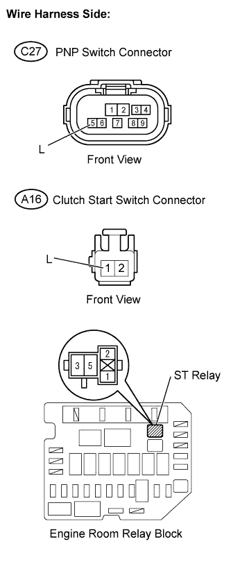
| 14.CHECK HARNESS AND CONNECTOR (PNP SWITCH OR CLUTCH START SWITCH - ST RELAY) |
Remove the ST relay from the engine room relay block.
Disconnect the C27 PNP switch connector (A/T).
Disconnect the A16 clutch start switch connector (M/T).
Check the resistance.
- Standard resistance (Check for open):
Tester Connections
| Specified Conditions
|
L (C27-5) - ST relay (2)
| Below 1 Ω
|
L (A16-1) - ST relay (2)
|
ST relay (1) - Body ground
|
- Standard resistance (Check for short):
Tester Connections
| Specified Conditions
|
L (C27-5) or ST relay (2) - Body ground
| 10 kΩ or higher
|
L (A16-1) or ST relay (2) - Body ground
|
Reinstall the ST relay.
Reconnect the PNP switch connector (A/T).
Reconnect the clutch start switch connector (M/T).
| | REPAIR OR REPLACE HARNESS OR CONNECTOR |
|
|
| OK |
|
|
|
| CHECK AND REPLACE STARTER RELAY AND STARTER |
|