TYPICAL MALFUNCTION THRESHOLDS
CHECK ANY OTHER DTCS OUTPUT (IN ADDITION TO DTC P0136, P0137, P0138 AND P0139)
READ VALUE USING TECHSTREAM (OUTPUT VOLTAGE OF HEATED OXYGEN SENSOR)
INSPECT HEATED OXYGEN SENSOR (CHECK FOR SHORT)
CHECK HARNESS AND CONNECTOR (CHECK FOR SHORT)
PERFORM ACTIVE TEST USING TECHSTREAM (CONTROL THE INJECTION VOLUME)
PERFORM ACTIVE TEST USING TECHSTREAM (CONTROL THE INJECTION VOLUME)
PERFORM ACTIVE TEST USING TECHSTREAM (CONTROL INJECTION VOLUME)
INSPECT HEATED OXYGEN SENSOR (HEATER RESISTANCE)
CHECK HARNESS AND CONNECTOR (HEATED OXYGEN SENSOR - ECM)
CHECK WHETHER DTC OUTPUT RECURS (DTC P0136, P0137 OR P0138)
CHECK WHETHER DTC OUTPUT RECURS (DTC P0136, P0137 OR P0138)
CHECK HARNESS OR CONNECTOR (CHECK FOR SHORT)
READ DTC OUTPUT (DTC P0139 OUTPUTS AGAIN)
DTC P0136 Oxygen Sensor Circuit Malfunction (Bank 1 Sensor 2) |
DTC P0137 Oxygen Sensor Circuit Low Voltage (Bank 1 Sensor 2) |
DTC P0138 Oxygen Sensor Circuit High Voltage (Bank 1 Sensor 2) |
DTC P0139 Oxygen Sensor Circuit Slow Response (Bank 1 Sensor 2) |
DESCRIPTION
- HINT:
- Sensor 2 refers to the sensor mounted behind the Three-Way Catalytic Converter (TWC) and located far from the engine assembly.
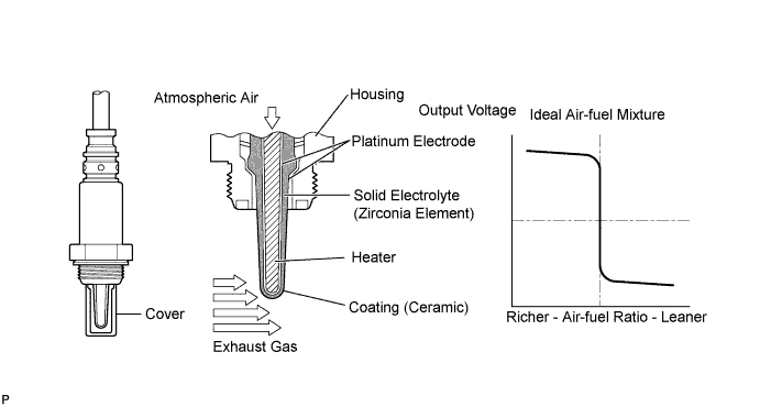
The HO2 sensor is located behind the TWC, and detects the oxygen concentration in the exhaust gas. Since the sensor is integrated with the heater that heats the sensing portion, it is possible to detect the oxygen concentration even when the intake air volume is low (the exhaust gas temperature is low).
When the air-fuel ratio becomes lean, the oxygen concentration in the exhaust gas is rich. The HO2 sensor informs the ECM that the post-TWC air-fuel ratio is lean (low voltage, i.e. less than 0.45 V).
Conversely, when the air-fuel ratio is richer than the stoichiometric air-fuel level, the oxygen concentration in the exhaust gas becomes lean. The HO2 sensor informs the ECM that the post-TWC air-fuel ratio is rich (high voltage, i.e. more than 0.45 V). The HO2 sensor has the property of changing its output voltage drastically when the air-fuel ratio is close to the stoichiometric level.
The ECM uses the supplementary information from the HO2 sensor to determine whether the air-fuel ratio after the TWC is rich or lean, and adjusts the fuel injection time accordingly. Thus, if the HO2 sensor is working improperly due to internal malfunctions, the ECM is unable to compensate for deviations in the primary air-fuel ratio control.
| DTC No. | DTC Detection Condition | Trouble Area |
| P0136 | Either condition is met:
|
|
| P0137 | Either condition is met:
|
|
| P0138 | Either condition is met:
|
|
| P0139 | Either condition is met:
|
|
| DTC No. | DTC Detection Condition | Trouble Area |
| P0136 | Not applicable | None |
| P0137 |
|
|
| P0138 | Not applicable | None |
| P0139 | Not applicable | None |
MONITOR DESCRIPTION
- Active Air-Fuel Ratio Control
The ECM usually performs air-fuel ratio feedback control so that the Air-Fuel Ratio (A/F) sensor output indicates a near stoichiometric air-fuel level. This vehicle includes active air-fuel ratio control in addition to regular air-fuel ratio control. The ECM performs active air-fuel ratio control to detect any deterioration in the Three-Way Catalytic Converter (TWC) and Heated Oxygen (HO2) sensor malfunctions (refer to the diagram below).
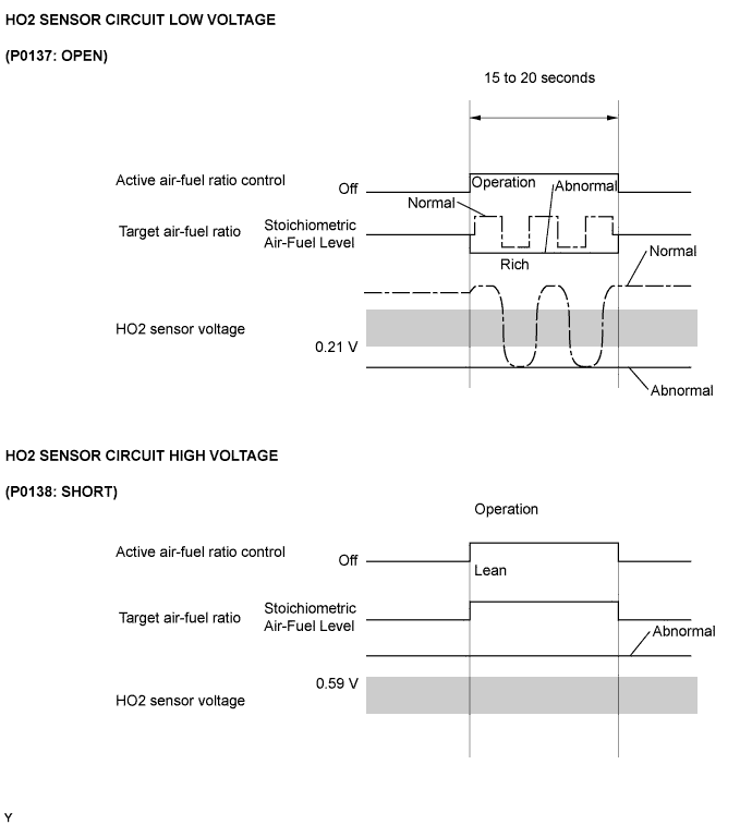
Active air-fuel ratio control is performed for approximately 15 to 20 seconds while driving with a warm engine. During active air-fuel ratio control, the air-fuel ratio is forcibly regulated to become lean or rich by the ECM. If the ECM detects a malfunction, one of the following DTCs is stored: DTC P0136 (abnormal voltage output), P0137 (open circuit) and P0138 (short circuit).
- Abnormal Voltage Output of HO2 Sensor (DTC P0136)
While the ECM is performing active air-fuel ratio control, the air-fuel ratio is forcibly regulated to become rich or lean. If the sensor is not functioning properly, the voltage output variation is small. For example, when the HO2 sensor voltage does not decrease to less than 0.21 V and does not increase to more than 0.59 V during active air-fuel ratio control, the ECM determines that the sensor voltage output is abnormal and stores DTC P0136.
- Open or Short in Heated Oxygen (HO2) Sensor Circuit (DTC P0137 or P0138)
During active air-fuel ratio control, the ECM calculates the Oxygen Storage Capacity (OSC)* of the Three-Way Catalytic Converter (TWC) by forcibly regulating the air-fuel ratio to become rich or lean. If the HO2 sensor has an open or short, or the voltage output of the sensor decreases significantly, the OSC indicates an extraordinarily high value. Even if the ECM attempts to continue regulating the air-fuel ratio to become rich or lean, the HO2 sensor output does not change.
While performing active air-fuel ratio control, when the target air-fuel ratio is rich and the HO2 sensor voltage output is 0.21 V or less (lean), the ECM interprets this as an abnormally low sensor output voltage and stores DTC P0137. When the target air-fuel ratio is lean and the voltage output is 0.59 V or more (rich) during active air-fuel ratio control, the ECM determines that the sensor voltage output is abnormally high, and stores DTC P0138.- HINT:
- DTC P0138 is also stored if the HO2 sensor voltage output is more than 1.2 V for 10 seconds or more.
- High or Low Impedance of Heated Oxygen (HO2) Sensor (DTC P0136 or P0137)
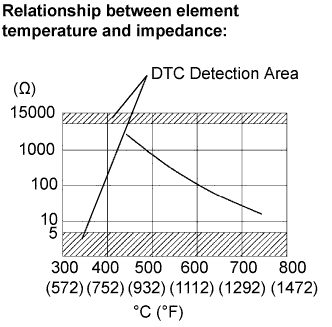
During normal air-fuel ratio feedback control, there are small variations in the exhaust gas oxygen concentration. In order to continuously monitor the slight variations in the HO2 sensor signal while the engine is running, the impedance* of the sensor is measured by the ECM. The ECM determines that there is a malfunction in the sensor when the measured impedance deviates from the standard range.
*: The effective resistance in an alternating current electrical circuit.- HINT:
- The impedance cannot be measured using an ohmmeter.
- DTC P0136 indicates the deterioration of the HO2 sensor. The ECM stores this DTC by calculating the impedance of the sensor when the typical enabling conditions are satisfied (2 driving cycle).
- DTC P0137 indicates an open or short circuit in the HO2 sensor (2 driving cycle). The ECM stores this DTC when the impedance of the sensor exceeds the threshold 15 kΩ.
- Abnormal Voltage Output of Heated Oxygen (HO2) Sensor During Fuel cut (DTC P0139)
The sensor output voltage drops to below 0.2 V (extremely lean status) immediately when the vehicle decelerates and fuel cut is operating. If the voltage does not drop to below 0.2 V for 7 seconds or more, or voltage does not drop from 0.35 V to 0.2 V for 1 second the ECM determines that the sensor's response feature has deteriorated, illuminates the MIL and stores a DTC.
MONITOR STRATEGY
| Related DTCs | P0136: Heated oxygen sensor output voltage (Abnormal voltage output) P0136: Heated oxygen sensor impedance (Low) P0137: Heated oxygen sensor output voltage (Low voltage) P0137: Heated oxygen sensor impedance (High) P0138: Heated oxygen sensor output voltage (High voltage) P0138: Heated oxygen sensor output voltage (Extremely high) P0139: Heated oxygen sensor output voltage during fuel cut |
| Required Sensors/Components (Main) | Heated oxygen sensor |
| Required Sensors/Components (Related) | Crankshaft position sensor, engine coolant temperature sensor, mass air flow meter and throttle position sensor |
| Frequency of Operation | Once per driving cycle: Active air-fuel ratio control detection, heated oxygen sensor output voltage during fuel cut Continuous: Others |
| Duration | 20 seconds: Active air-fuel ratio control detection 90 seconds: Heated oxygen sensor impedance (High) 30 seconds: Heated oxygen sensor impedance (Low) 10 seconds: Output voltage (Stuck high) 7 seconds: Heated oxygen sensor voltage during fuel cut |
| MIL Operation | 2 driving cycles |
| Sequence of Operation | None |
TYPICAL ENABLING CONDITIONS
| Monitor runs whenever following DTCs not present | P0016 (VVT system - misalignment) P0031, P0032 (A/F Sensor heater) P0037, P0038 (HO2 Sensor heater) P0100, P0102, P0103 (MAF meter) P0110, P0112, P0113 (IAT sensor) P0115, P0117, P0118 (ECT sensor) P0120 - P0123, P0220, P0222, P0223, P2135 (TP sensor) P0125 (Insufficient ECT for Closed Loop) P0128 (Thermostat) P0171, P0172 (Fuel system) P0301 - P0304 (Misfire) P0335 (CKP sensor) P0340 (CMP sensor) P0450 - P0453 (EVAP system) P0500 (VSS) P0722 (VSS) P2195, P2196 (A/F sensor) P2237 - P2239, P2252, P2253 (A/F sensor) P2A00 (A/F sensor) |
| Active air-fuel ratio control | Executing |
| Active air-fuel ratio control begins when all of following conditions met: | - |
| Battery voltage | 11 V or more |
| Intake air temperature | -10°C (14°F) or more |
| Engine coolant temperature | 75°C (167°F) or more |
| Idling | OFF |
| Engine RPM | Less than 4000 rpm |
| A/F sensor status | Activated |
| Fuel system status | Closed loop |
| Fuel cut | OFF |
| Engine load | 10 to 80% |
| Shift position | 4th or 5th (M/T) 3rd or 4th (A/T) |
| Battery voltage | 11 V or more |
| Estimated rear oxygen sensor temperature | Less than 700°C (1292°F) |
| ECM monitor | Completed |
| DTC P0606 | Not stored |
| Battery voltage | 11 V or more |
| Estimated rear oxygen sensor temperature | 450 to 750°C (842 to 1382°F) |
| DTC P0606 | Not stored |
| Battery voltage | 11 V or more |
| Time after engine start | 2 seconds or more |
| Engine coolant temperature | 75°C (167°F) or more |
| Estimated catalyst temperature | 400°C (752°F) or more |
| Fuel cut | ON |
TYPICAL MALFUNCTION THRESHOLDS
| Either of following conditions met: | 1 or 2 |
| 1. All of following conditions (a), (b) and (c) met | - |
| (a) Commanded air-fuel ratio | 14.3 or less |
| (b) Heated oxygen sensor voltage | 0.21 to 0.59 V |
| (c) OSC (Oxygen Storage Capacity of Catalyst) | 1.7 g or more |
| 2. All of following conditions (d), (e) and (f) met | - |
| (d) Commanded air-fuel ratio | 14.9 or more |
| (e) Heated oxygen sensor voltage | 0.21 to 0.59 V |
| (f) OSC | 1.7 g or more |
| All of following conditions (a), (b) and (c) met | - |
| (a) Commanded air-fuel ratio | 14.3 or less |
| (b) Rear HO2 sensor voltage | Less than 0.21 V |
| (c) OSC | 1.7 g or more |
| All of following conditions (a), (b) and (c) met | - |
| (a) Commanded air-fuel ratio | 14.9 or more |
| (b) Heated oxygen sensor voltage | More than 0.59 V |
| (c) OSC | 1.7 g or more |
| Duration of following condition met | 30 seconds or more |
| Heated oxygen sensor impedance | Less than 5 Ω |
| Duration of following condition met | 90 seconds or more |
| Heated oxygen sensor impedance | 15 kΩ or more |
| Duration of following condition met | 10 seconds or more |
| Heated oxygen sensor voltage | 1.2 V or more |
| Duration until rear heated oxygen sensor voltage drops to 0.2 V after fuel cut | 7 seconds or more |
| Duration until rear heated oxygen sensor voltage drops from 0.35 V to 0.2 V during fuel cut | 1 second or more |
COMPONENT OPERATING RANGE
| Duration of following condition met | 30 seconds or more |
| Heated oxygen sensor voltage | Varies between 0.1 and 0.9 V |
MONITOR RESULT
Refer to Checking Monitor Status (YARIS_NCP93 RM000000PDR0A3X.html).CONFIRMATION DRIVING PATTERN
- P0136, P0137 and P0138

- Connect the Techstream to the DLC3.
- Turn the ignition switch to ON and turn the Techstream on.
- Clear DTCs (even if no DTCs are stored, perform the clear DTC operation).
- Turn the ignition switch off and wait for at least 30 seconds.
- Turn the ignition switch to ON and turn the Techstream on [A].
- Start the engine and warm it up until the ECT reaches 75°C (167°F) or higher [B].
- With the transmission in 4th gear or higher, drive the vehicle at 60 to 120 km/h (40 to 75 mph) for 10 minutes or more [C].
- CAUTION:
- When performing the confirmation driving pattern, obey all speed limits and traffic laws.
- Enter the following menus: Powertrain / Engine and ECT / Trouble Codes [D].
- Read pending DTCs.
- HINT:
- If a pending DTC is output, the system is malfunctioning.
- If a pending DTC is not output, perform the following procedure.
- Enter the following menus: Powertrain / Engine and ECT / Utility / All Readiness.
- Input the DTC: P0136, P0137 or P0138.
- Check the DTC judgment result.
Techstream Display Description NORMAL - DTC judgment completed
- System normal
ABNORMAL - DTC judgment completed
- System abnormal
INCOMPLETE - DTC judgment not completed
- Perform driving pattern after confirming DTC enabling conditions
N/A - Unable to perform DTC judgment
- Number of DTCs which do not fulfill DTC preconditions has reached ECU memory limit
- HINT:
- If the judgment result shows NORMAL, the system is normal.
- If the judgment result shows ABNORMAL, the system has a malfunction.
- If the judgment result shows INCOMPLETE or N/A, perform steps [C] through [D].
- DTC judgment completed
- If no pending DTC is output, perform a universal trip and check for permanent DTCs (YARIS_NCP93 RM000000PDK0QGX.html).
- HINT:
- If a permanent DTC is output, the system is malfunctioning.
- If no permanent DTC is output, the system is normal.
- P0139

- Connect the Techstream to the DLC3.
- Turn the ignition switch to ON and turn the Techstream on.
- Clear DTCs (even if no DTCs are stored, perform the clear DTC operation).
- Turn the ignition switch off and wait for at least 30 seconds.
- Turn the ignition switch to ON and turn the Techstream on [A].
- Start the engine and warm it up until the ECT reaches 75°C (167°F) or higher [B].
- Drive the vehicle at 60 km/h (40 mph), and then decelerate the vehicle by releasing the accelerator pedal for 8 seconds or more to perform the fuel-cut [C].
- CAUTION:
- When performing the confirmation driving pattern, obey all speed limits and traffic laws.
- Enter the following menus: Powertrain / Engine and ECT / Trouble Codes [D].
- Read DTCs.
- HINT:
- If a pending DTC or current DTC is output, the system is malfunctioning.
- If a pending DTC or current DTC is not output, perform the following procedure.
- Enter the following menus: Powertrain / Engine and ECT / Utility / All Readiness.
- Input the DTC: P0139.
- Check the DTC judgment result.
Techstream Display Description NORMAL - DTC judgment completed
- System normal
ABNORMAL - DTC judgment completed
- System abnormal
INCOMPLETE - DTC judgment not completed
- Perform driving pattern after confirming DTC enabling conditions
N/A - Unable to perform DTC judgment
- Number of DTCs which do not fulfill DTC preconditions has reached ECU memory limit
- HINT:
- If the judgment result shows NORMAL, the system is normal.
- If the judgment result shows ABNORMAL, the system has a malfunction.
- If the judgment result shows INCOMPLETE or N/A, shift the transmission to 2nd gear (2nd range), and then perform steps [C] and [D] again.
- DTC judgment completed
- If no pending DTC is output, perform a universal trip and check for permanent DTCs (YARIS_NCP93 RM000000PDK0QGX.html).
- HINT:
- If a permanent DTC is output, the system is malfunctioning.
- If no permanent DTC is output, the system is normal.
WIRING DIAGRAM
Refer to DTC P2195 (YARIS_NCP93 RM000000WC40K6X_07.html).INSPECTION PROCEDURE
- HINT:
- Malfunctioning areas can be identified by performing the Control the Injection Volume function provided in the Active Test. The Control the Injection Volume function can help to determine whether the Air-Fuel Ratio (A/F) sensor, Heated Oxygen (HO2) sensor and other potential trouble areas are malfunctioning.
- The following instructions describe how to conduct the Control the Injection Volume operation using a Techstream.
- Connect the Techstream to the DLC3.
- Start the engine.
- Turn the Techstream on.
- Warm up the engine at an engine speed of 2500 rpm for approximately 90 seconds.
- Enter the following menus: Powertrain / Engine and ECT / Active Test / Control the Injection Volume.
- Perform the Active Test operation with the engine in an idling condition (press the RIGHT or LEFT button to change the fuel injection volume.)
- Monitor the output voltages of the A/F and HO2 sensors (AFS Voltage B1S1 and O2S B1S2) displayed on the Techstream.
- HINT:
- Change the fuel injection volume within the range of -12% to +12%. The injection volume can be changed in fine gradations.
- Each sensor reacts in accordance with increases and decreases in the fuel injection volume.
| Techstream Display (Sensor) | Injection Volume | Status | Voltage |
| AFS Voltage B1S1 (A/F) | +12% | Rich | Less than 3.1 V |
| -12% | Lean | More than 3.4 V | |
| O2S B1S2 (HO2) | +12% | Rich | More than 0.55 V |
| -12% | Lean | Less than 0.4 V |
- NOTICE:
- The Air-Fuel Ratio (A/F) sensor has an output delay of a few seconds and the Heated Oxygen (HO2) sensor has a maximum output delay of approximately 20 seconds.
| Case | A/F Sensor (Sensor 1) Output Voltage | HO2 Sensor (Sensor 2) Output Voltage | Main Suspected Trouble Area |
| 1 |  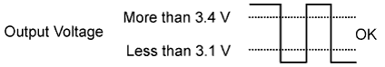 | 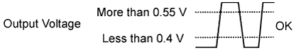 | - |
| 2 |  | |
|
| 3 | | |
|
| 4 | | |
|
- Following the Control the Injection Volume procedure enables technicians to check and graph the voltage outputs of both the A/F and HO2 sensors.
- To display the graph, enter the following menus: Powertrain / Engine and ECT / Active Test / Control the Injection Volume / AFS Voltage B1S1 and O2S B1S2; then press the graph button on the Data List view.
- NOTICE:
- Inspect the fuses for circuits related to this system before performing the following inspection procedure.
- HINT:
- Sensor 1 refers to the sensor closest to the engine assembly.
- Sensor 2 refers to sensor farthest away from the engine assembly.
- Read freeze frame data using the Techstream. The ECM records vehicle and driving condition information as freeze frame data the moment a DTC is stored. When troubleshooting, freeze frame data can help determine if the vehicle was moving or stationary, if the engine was warmed up or not, if the air fuel ratio was lean or rich, and other data from the time the malfunction occurred.
| 1.CHECK ANY OTHER DTCS OUTPUT (IN ADDITION TO DTC P0136, P0137, P0138 AND P0139) |
Connect the Techstream to the DLC3.
Turn the ignition switch to ON.
Turn the Techstream on.
Enter the following menus: Powertrain / Engine and ECT / Trouble Codes.
Read DTCs.
Result Result Proceed to DTC P0138 is output A DTC P0137 is output B DTC P0136 is output C DTC P0139 is output D DTC P0136, P0137 or P0138 and other DTCs are output E - HINT:
- If any DTCs other than P0136, P0137 or P0138 are output, troubleshoot those DTCs first.
|
| ||||
|
| ||||
|
| ||||
|
| ||||
| A | |
| 2.READ VALUE USING TECHSTREAM (OUTPUT VOLTAGE OF HEATED OXYGEN SENSOR) |
Connect the Techstream to the DLC3.
Turn the ignition switch to ON.
Turn the Techstream on.
Enter the following menus: Powertrain / Engine and ECT / Data List / O2S B1S2.
Allow the engine to idle.
Read the Heated Oxygen (HO2) sensor output voltage while idling.
Result HO2 Sensor Output Voltage Proceed to 1.0 V or higher A Below 1.0 V B
|
| ||||
| A | |
| 3.INSPECT HEATED OXYGEN SENSOR (CHECK FOR SHORT) |
 |
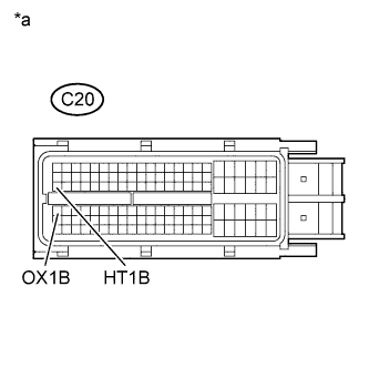
Disconnect the HO2 sensor connector.
Measure the resistance according to the value(s) in the table below.
- Standard resistance:
Tester Connection Condition Specified Condition +B (2) - E2 (4) Always 10 kΩ or higher +B (2) - OX1B (3) Always 10 kΩ or higher
Text in Illustration *a Front view of wire connector
(to Heated Oxygen Sensor (Sensor 2))
Reconnect the sensor connector.
|
| ||||
| OK | |
| 4.CHECK HARNESS AND CONNECTOR (CHECK FOR SHORT) |
 |
Disconnect the ECM connector.
Measure the resistance according to the value(s) in the table below.
- Standard resistance:
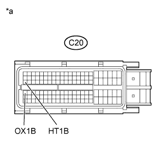
Tester Connection Condition Specified Condition HT1B (C20-47) - OX1B (C20-64) Always 10 kΩ or higher
Text in Illustration *a Front view of wire connector
(to ECM Connector)
Reconnect the ECM connector.
|
| ||||
| OK | ||
| ||
| 5.PERFORM ACTIVE TEST USING TECHSTREAM (CONTROL THE INJECTION VOLUME) |
Connect the Techstream to the DLC3.
Start the engine.
Turn the Techstream on.
Warm up the engine.
Enter the following menus: Powertrain / Engine and ECT / Active Test / Control the Injection Volume.
Change the fuel injection volume using the Techstream, monitoring the voltage output of Air-Fuel Ratio (A/F) and HO2 sensors displayed on the Techstream.
- HINT:
- Change the fuel injection volume within the range of -12% and +12%. The injection volume can be changed in fine gradations within the range.
- The A/F sensor is displayed as AFS Voltage B1S1, and the HO2 sensor is displayed as O2S B1S2, on the Techstream.
- The air fuel ratio sensor has an output delay of a few seconds and the heated oxygen sensor has a maximum output delay of approximately 20 seconds.
- If the sensor output voltage does not change (almost no reaction) while performing the Active Test, the sensor may be malfunctioning.
| Techstream Display (Sensor) | Voltage Variation | Proceed to |
| AFS Voltage B1S1 (A/F) | Alternates between more and less than 3.3 V | OK |
| Remains at more than 3.3 V | NG | |
| Remains at less than 3.3 V | NG |
- HINT:
- A normal HO2 sensor voltage (O2S B1S2) reacts in accordance with increases and decreases in fuel injection volumes. When the A/F sensor voltage remains at either less or more than 3.3 V despite the HO2 sensor indicating a normal reaction, the A/F sensor is malfunctioning.

|
| ||||
| OK | |
| 6.INSPECT AIR FUEL RATIO SENSOR |
- HINT:
- This A/F sensor test is to check the A/F sensor current during the fuel cut. When the sensor is normal, the sensor current will indicate below 3.6 mA in this test.
Connect the Techstream to the DLC3.
Turn the ignition switch to ON.
Turn the Techstream on.
Drive the vehicle by the drive pattern as listed below:
Warm up the engine until the engine coolant temperature reaches 75°C (167°F) or more.
Drive the vehicle at 60 km/h (40 mph) or more and decelerate the vehicle for 8 seconds or more.
Repeat the deceleration above at least 3 times.

Enter the following menus: Powertrain / Engine and ECT / Monitor / Current Monitor / O2 Sensor / Details.
Confirm that RANGE B1S1 is either Pass or Fail. If the Techstream shows Incomplete, recheck RANGE B1S1 after performing the drive pattern.
Read the Test Value of the RANGE B1S1.
- Standard current:
- Less than 3.6 mA
- HINT:
- If the Techstream shows Incomplete again, increase the vehicle speed and use the second gear to decelerate the vehicle.
- NOTICE:
- Do not turn the ignition switch off during this step because the test results will be lost.
|
| ||||
|
| ||||
| 7.PERFORM ACTIVE TEST USING TECHSTREAM (CONTROL THE INJECTION VOLUME) |
Connect the Techstream to the DLC3.
Turn the ignition switch to ON.
Turn the Techstream on.
Start the engine and warm it up.
Enter the following menus: Powertrain / Engine and ECT / Active Test / Control the Injection Volume / O2S B1S2.
Change the fuel injection volume using the Techstream, monitoring the voltage output of the HO2 sensor displayed on the Techstream.
- HINT:
- Change the fuel injection volume within the range of -12% to +12%. The injection volume can be changed in fine gradations within this range.
- The air fuel ratio sensor has an output delay of a few seconds and the heated oxygen sensor has a maximum output delay of approximately 20 seconds.
- Standard voltage:
- Fluctuates between 0.4 V or less and 0.55 V or more.
|
| ||||
| OK | |
| 8.PERFORM ACTIVE TEST USING TECHSTREAM (CONTROL INJECTION VOLUME) |
Connect the Techstream to the DLC3.
Start the engine.
Turn the Techstream on.
Warm up the engine.
Enter the following menus: Powertrain / Engine and ECT / Active Test / Control the Injection Volume.
Change the fuel injection volume using the Techstream, monitoring the voltage output of Air-Fuel Ratio (A/F) and HO2 sensor displayed on the Techstream.
- HINT:
- Change the fuel injection volume within the range of -12% and +12%. The injection volume can be changed in fine gradations within the range.
- The A/F sensor is displayed as AFS Voltage B1S1, and the HO2 sensor is displayed as O2S B1S2, on the Techstream.
- The air fuel ratio sensor has an output delay of a few seconds and the heated oxygen sensor has a maximum output delay of approximately 20 seconds.
- If the sensor output voltage does not change (almost no reaction) while performing the Active Test, the sensor may be malfunctioning.
| Techstream Display (Sensor) | Voltage Variation | Proceed to |
| AFS Voltage B1S1 (A/F) | Alternates between more and less than 3.3 V | OK |
| Remains at more than 3.3 V | NG | |
| Remains at less than 3.3 V | NG |
- HINT:
- A normal HO2 sensor voltage (O2S B1S2) reacts in accordance with increases and decreases in fuel injection volumes. When the A/F sensor voltage remains at either less or more than 3.3 V despite the HO2 sensor indicating a normal reaction, the A/F sensor is malfunctioning.
|
| ||||
| OK | ||
| ||
| 9.CHECK FOR EXHAUST GAS LEAK |
Check for exhaust gas leak.
- OK:
- No gas leak.
|
| ||||
| OK | |
| 10.INSPECT HEATED OXYGEN SENSOR (HEATER RESISTANCE) |
Inspect the HO2 sensor (YARIS_NCP93 RM000001CK803HX.html).
|
| ||||
| OK | |
| 11.CHECK HARNESS AND CONNECTOR (HEATED OXYGEN SENSOR - ECM) |
Disconnect the HO2 sensor connector.
Disconnect the ECM connector.
Measure the resistance according to the value(s) in the table below.
- Standard resistance (Check for open):
Tester Connection Condition Specified Condition HT1B (D28-1) - HT1B (C20-47) Always Below 1 Ω OX1B (D28-3) - OX1B (C20-64) Always Below 1 Ω E2 (D28-4) - EX1B (C20-87) Always Below 1 Ω
- Standard resistance (Check for short):
Tester Connection Condition Specified Condition HT1B (D28-1) or HT1B (C20-47) - Body ground Always 10 kΩ or higher OX1B (D28-3) or OX1B (C20-64) - Body ground Always 10 kΩ or higher E2 (D28-4) or EX1B (C20-87) - Body ground Always 10 kΩ or higher
Reconnect the HO2 sensor connector.
Reconnect the ECM connector.
|
| ||||
| OK | |
| 12.REPLACE HEATED OXYGEN SENSOR |
Replace the HO2 sensor (YARIS_NCP93 RM000001CMD00WX.html).
| NEXT | |
| 13.CHECK WHETHER DTC OUTPUT RECURS (DTC P0136, P0137 OR P0138) |
Connect the Techstream to the DLC3.
Turn the ignition switch to ON.
Turn the Techstream on.
Clear the DTCs (even if no DTCs are stored, perform the Clear DTC procedure) (YARIS_NCP93 RM000000PDK0QGX.html).
Turn the ignition switch off and wait for at least 30 seconds.
Turn the ignition switch to ON.
Turn the Techstream on.
Start the engine and warm it up.
Drive the vehicle in accordance with the driving pattern described in the Confirmation Driving Pattern.
Check the DTC judgment.
Result Result Proceed to ABNORMAL (P0136, P0137 or 0138 is output) A NORMAL (No DTC output) B
|
| ||||
| A | ||
| ||
| 14.REPLACE AIR-FUEL RATIO SENSOR |
Replace the A/F ratio sensor (YARIS_NCP93 RM000001CKA00YX.html).
| NEXT | |
| 15.CHECK WHETHER DTC OUTPUT RECURS (DTC P0136, P0137 OR P0138) |
Connect the Techstream to the DLC3.
Turn the ignition switch to ON.
Turn the Techstream on.
Clear the DTCs (even if no DTCs are stored, perform the Clear DTC procedure) (YARIS_NCP93 RM000000PDK0QGX.html).
Turn the ignition switch off and wait for at least 30 seconds.
Turn the ignition switch to ON.
Turn the Techstream on.
Start the engine and warm it up.
Drive the vehicle in accordance with the driving pattern described in the Confirmation Driving Pattern.
Check the DTC judgment.
Result Result Proceed to ABNORMAL (P0136, P0137 or 0138 is output) A NORMAL (No DTC output) B
|
| ||||
| A | ||
| ||
| 16.CHECK FOR EXHAUST GAS LEAK |
Check for exhaust gas leak.
- OK:
- No gas leak.
|
| ||||
| OK | |
| 17.CHECK HARNESS OR CONNECTOR (CHECK FOR SHORT) |
 |
Turn the ignition switch off and wait for 5 minutes.
Disconnect the ECM connector.
Measure the resistance according to the value(s) in the table below.
- Standard resistance:
Tester Connection Condition Specified Condition HT1B (C20-47) - OX1B (C20-64) Always 10 kΩ or higher
Text in Illustration *a Front view of wire harness connector
(to ECM)
Reconnect the ECM connector.
|
| ||||
| OK | |
| 18.READ DTC OUTPUT (DTC P0139 OUTPUTS AGAIN) |
Connect the Techstream to the DLC3.
Turn the ignition switch ON.
Turn the Techstream on.
Clear the DTCs (even if no DTCs are stored, perform the Clear DTC procedure) (YARIS_NCP93 RM000000PDK0QGX.html).
Turn the ignition switch off and wait for at least 30 seconds.
Turn the ignition switch to ON.
Turn the Techstream on.
Start the engine and warm it up.
Drive the vehicle in accordance with the driving pattern described in the Confirmation Driving Pattern.
Check the STATUS is NORMAL. If STATUS is INCOMPLETE, perform the drive pattern increasing the vehicle speed and using the second gear to decelerate the vehicle.
Result Result Proceed to ABNORMAL (P0139 is output) A NORMAL (No DTC output) B
|
| ||||
| A | ||
| ||