DESCRIPTION
WIRING DIAGRAM
INSPECTION PROCEDURE
CHECK THE ENGINE SWITCH CONDITION
CHECK FOR DTC
CHECK CRANKING FUNCTION
READ VALUE USING TECHSTREAM (STARTER CONTROL)
PERFORM ACTIVE TEST USING TECHSTREAM (ST RELAY)
INSPECT ST RELAY
CHECK HARNESS AND CONNECTOR (ST RELAY TERMINAL VOLTAGE AND RESISTANCE)
CHECK HARNESS AND CONNECTOR (ST RELAY - STARTER)
CHECK HARNESS AND CONNECTOR (BATTERY - STARTER)
READ VALUE USING TECHSTREAM (PARK/NEUTRAL POSITION SWITCH)
READ VALUE USING TECHSTREAM (S CODE)
READ VALUE USING TECHSTREAM (L CODE)
READ VALUE USING TECHSTREAM (IMMOBILISER SYSTEM STATUS)
CHECK HARNESS AND CONNECTOR (MAIN BODY ECU - BODY GROUND)
INSPECT PARK/NEUTRAL POSITION SWITCH
CHECK HARNESS AND CONNECTOR (MAIN BODY ECU - PARK/NEUTRAL POSITION SWITCH)
CHECK HARNESS AND CONNECTOR (PARK/NEUTRAL POSITION SWITCH - ECM)
INSPECT ST RELAY
CHECK HARNESS AND CONNECTOR (ECM - ST RELAY)
INSPECT ST CUT RELAY
CHECK HARNESS AND CONNECTOR (ST CUT RELAY - ECM)
CHECK HARNESS AND CONNECTOR (ST CUT RELAY - MAIN BODY ECU)
CHECK HARNESS AND CONNECTOR (ECM - ST RELAY)
REGISTER RECOGNITION CODE (ECU CODE)
CHECK CRANKING FUNCTION
REPLACE CERTIFICATION ECU (SMART KEY ECU ASSEMBLY)
KEY REGISTRATION
CHECK CRANKING FUNCTION
REGISTER RECOGNITION CODE (ECU CODE)
CHECK CRANKING FUNCTION
REPLACE STEERING LOCK ECU
REGISTER RECOGNITION CODE (ECU CODE)
CHECK CRANKING FUNCTION
READ VALUE USING TECHSTREAM (ENGINE START REQUEST)
SMART KEY SYSTEM (for Start Function) - Engine does not Start |
DESCRIPTION
| ENGINE START SYSTEM FUNCTION |
If the engine switch is pressed with the shift lever is in P or N and the brake pedal depressed, the main body ECU (instrument panel junction block) determines that it is an engine start request.
The certification ECU (smart key ECU assembly) and other ECUs perform key verification via the LIN communication line.
The main body ECU (instrument panel junction block) activates the ACC relay.
The main body ECU (instrument panel junction block) activates the IG1 and IG2 relays.
The certification ECU (smart key ECU assembly) outputs a steering UNLOCK signal. The signal is sent to the main body ECU (instrument panel junction block) via the steering lock ECU.
The main body ECU (instrument panel junction block) sends an engine start request signal to the ECM.
The ECM sends an ACC cut request signal to the main body ECU (instrument panel junction block).
The ECM and main body ECU (instrument panel junction block) activate the ST relay.
The main body ECU (instrument panel junction block) deactivates the ACC relay until the main body ECU (instrument panel junction block) detects an engine start.
When engine revolution speed reaches 1200 rpm, the ECM determines that the engine has been started.
The ECM stops sending an ACC cut request signal to the main body ECU.
The main body ECU (instrument panel junction block) reactivates the ACC relay and turns off the engine switch indicator light, when engine revolution speed reaches 800 rpm.
Symbol of Main Body ECU
| Signal
|
STP
| Stop light switch ON signal
| Input
|
SSW1/SSW2
| Engine switch ON signal
| Input
|
ACCD
| ACC relay operation signal
| Output
|
SLP
| Steering lock actuator position signal
| Input
|
IG1D
| IG1 relay operation signal
| Output
|
IG2D
| IG2 relay operation signal
| Output
|
STR2
| ST relay operation signal (Sub)
| Output
|
STR
| Park/Neutral position switch signal
| Input
|
TACH
| Engine start detection signal
| Input
|
STSW
| Starter activation request signal
| Output
|
ACCR
| ACC cut request signal
| Input
|
Symbol of ECM
| Signal
|
ACCR
| ACC cut request signal
| Output
|
TACH
| Engine revolution speed signal
| Output
|
STSW
| Starter activation request signal
| Input
|
STAR
| ST relay operation signal (Main)
| Output
|
STA
| Starter activation signal
| Input
|
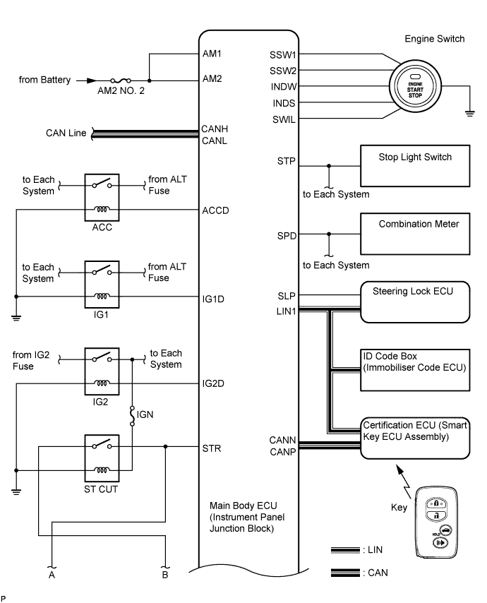
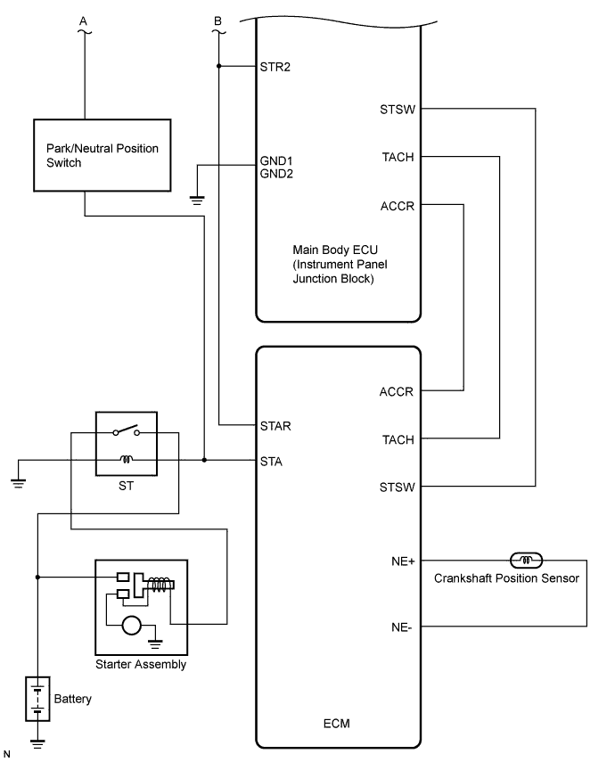
WIRING DIAGRAM
See CRANKING HOLDING FUNCTION CIRCUIT (COROLLA_ZRE142 RM000001FLC087X_02.html).
INSPECTION PROCEDURE
| EMERGENCY ENGINE START CONTROL |
If there is a malfunction in the stop light switch or STOP fuse, their signals may not be correctly transmitted to the main body ECU (instrument panel junction block). This may result in the engine not starting even if the engine switch is pressed while the brake pedal is depressed and the shift lever is in P.
To activate the starter:
Turn the engine switch from off to on (ACC).
Hold pressing and hold the engine switch for 15 seconds.
- HINT:
- After the main body ECU (instrument panel junction block), certification ECU (smart key ECU assembly), steering lock ECU, ID code box (immobiliser code ECU) and/or ECM are/is replaced, perform the registration procedures for the engine immobiliser system (COROLLA_ZRE142 RM000000QYF05AX.html).
| 1.CHECK THE ENGINE SWITCH CONDITION |
Check the power source mode changes.
When the key is inside the vehicle and the shift lever is in P, check that the power source mode changes.
- OK:
- off → on (ACC) → on (IG) → off
Clear the DTCs (COROLLA_ZRE142 RM000000YEH0CGX.html).
Check for DTCs again.
Proceed to the next step based on the inspection result.
- Result:
Result
| Proceed to
|
No DTC is output
| A
|
Smart key system (for start function) DTCs are output
| B
|
Steering lock DTCs are output
| C
|
Engine immobiliser system DTCs are output
| D
|
Vehicle stability control system DTCs are output
| E
|
| 3.CHECK CRANKING FUNCTION |
Check the engine cranking function.
When there is fuel in the fuel tank, the key is inside the vehicle, and the shift lever is in P, check that depressing the brake pedal and pressing the engine switch crank the engine.
- Result:
Result
| Proceed to
|
Engine cranks
| A
|
Engine does not crank
| B
|
| 4.READ VALUE USING TECHSTREAM (STARTER CONTROL) |
Connect the Techstream to the DLC3.
Turn the engine switch on (IG).
Read the Data List according to the displays on the Techstream screen.
Engine and ECTTester Display
| Measurement Item/Range
| Normal Condition
| Diagnostic Note
|
Starter Control
| Starter switch signal / ON or OFF
| ON: Engine switch on (ST)
OFF: Engine switch except on (ST)
| -
|
- Standard:
Engine switch condition
| Tester display
|
When engine switch is on (ST)
| ON
|
When engine switch is except on (ST)
| OFF
|
| 5.PERFORM ACTIVE TEST USING TECHSTREAM (ST RELAY) |
Connect the Techstream to the DLC3.
Turn the engine switch on (IG).
Perform Active Test according to the prompts displayed on the Techstream.
Engine and ECTTester Display
| Test Part
| Control Range
| Diagnostic Note
|
Activate the ST Relay
| Starter
| ON or OFF
| -
|
Measure the voltage according to the value(s) in the table below.
- Standard Voltage:
Tester Connection
| Condition
| Specified Condition
|
Relay block No. 8 ST relay terminal 2 - Relay block No. 8 ST relay terminal 1
| When ST relay is ON by Active test using Techstream
| 8 to 14 V
|
Relay block No. 8 ST relay terminal 2 - Relay block No. 8 ST relay terminal 1
| When ST relay is OFF by Active test using Techstream
| Below 1 V
|
Remove the ST relay from the relay block No. 8.
Measure the resistance according to the value(s) in the table below.
- Standard Resistance:
Tester Connection
| Condition
| Specified Condition
|
3 - 5
| When battery voltage is not applied to terminals 1 and 2
| 10 kΩ or higher
|
3 - 5
| When battery voltage is applied to terminals 1 and 2
| Below 1 Ω
|
| 7.CHECK HARNESS AND CONNECTOR (ST RELAY TERMINAL VOLTAGE AND RESISTANCE) |
Measure the voltage according to the value(s) in the table below.
- Standard Voltage:
Tester Connection
| Condition
| Specified Condition
|
Relay block No. 8 ST relay terminal 5 - Body ground
| Always
| 11 to 14 V
|
Measure the resistance according to the value(s) in the table below.
- Standard Resistance:
Tester Connection
| Condition
| Specified Condition
|
Relay block No. 8 ST relay terminals 1 - Body ground
| Always
| Below 1 Ω
|
| | REPAIR OR REPLACE HARNESS OR CONNECTOR, OR REPLACE FUSE |
|
|
| 8.CHECK HARNESS AND CONNECTOR (ST RELAY - STARTER) |
Disconnect the B8 connector.
Measure the resistance according to the value(s) in the table below.
- Standard Resistance:
Tester Connection
| Condition
| Specified Condition
|
Relay block No. 8 ST relay terminal 3 - B8-1
| Always
| Below 1 Ω
|
Relay block No. 8 ST relay terminal 3 or B8-1 - Body ground
| Always
| 10 kΩ or higher
|
| | REPAIR OR REPLACE HARNESS OR CONNECTOR (ST RELAY - STARTER) |
|
|
| 9.CHECK HARNESS AND CONNECTOR (BATTERY - STARTER) |
Disconnect the B4 connector.
Measure the voltage according to the value(s) in the table below.
- Standard Voltage:
Tester Connection
| Condition
| Specified Condition
|
B4-1 - Body ground
| Always
| 11 to 14 V
|
| | REPAIR OR REPLACE HARNESS OR CONNECTOR (BATTERY - STARTER) |
|
|
| 10.READ VALUE USING TECHSTREAM (PARK/NEUTRAL POSITION SWITCH) |
Connect the Techstream to the DLC3.
Turn the engine switch on (IG).
Read the Data List according to the displays on the Techstream screen.
Main BodyTester Display
| Measurement Item/Range
| Normal Condition
| Diagnostic Note
|
N SW / C SW
| Park/Neutral position switch / ON or OFF
| ON: Shift position is P or N
OFF: Shift position is not P nor N
| -
|
- OK:
- "ON" (Shift position is P or N) and "OFF" (Shift position is not P nor N) appear on the screen.
| 11.READ VALUE USING TECHSTREAM (S CODE) |
Connect the Techstream to the DLC3.
- HINT:
- When using the Techstream with the engine switch off, turn on and off any of the door courtesy light switches repeatedly at 1.5 second intervals or less until communication between the Techstream and vehicle starts.
Turn the engine switch on (IG).
Read the Data List according to the displays on the Techstream.
Smart KeyTester Display
| Measurement Item/Range
| Normal Condition
| Diagnostic Note
|
S Code Chk
| S code check / OK or NG
| OK: Normal
NG: Malfunction
| -
|
- OK:
- "OK" is displayed on the screen.
| 12.READ VALUE USING TECHSTREAM (L CODE) |
Connect the Techstream to the DLC3.
- HINT:
- When using the Techstream with the engine switch off, turn on and off any of the door courtesy light switches repeatedly at 1.5 second intervals or less until communication between the Techstream and vehicle starts.
Turn the engine switch on (IG).
Read the Data List according to the displays on the Techstream.
Smart KeyTester Display
| Measurement Item/Range
| Normal Condition
| Diagnostic Note
|
L Code Chk
| L code check / OK or NG
| OK: Normal
NG: Malfunction
| -
|
- OK:
- "OK" is displayed on the screen.
| 13.READ VALUE USING TECHSTREAM (IMMOBILISER SYSTEM STATUS) |
Connect the Techstream to the DLC3.
- HINT:
- When using the Techstream with the engine switch off, turn on and off any of the door courtesy light switches repeatedly at 1.5 second intervals or less until communication between the Techstream and vehicle starts.
Turn the engine switch on (IG).
Read the Data List according to the displays on the Techstream.
ImmobiliserTester Display
| Measurement Item/Range
| Normal Condition
| Diagnostic Note
|
Immobiliser
| Immobiliser system status / SET or UNSET
| UNSET: Engine switch ON
SET: Without key
| -
|
- OK:
- UNSET (Engine switch ON) appears on the screen.
| OK |
|
|
|
| REPLACE MAIN BODY ECU (INSTRUMENT PANEL JUNCTION BLOCK) |
|
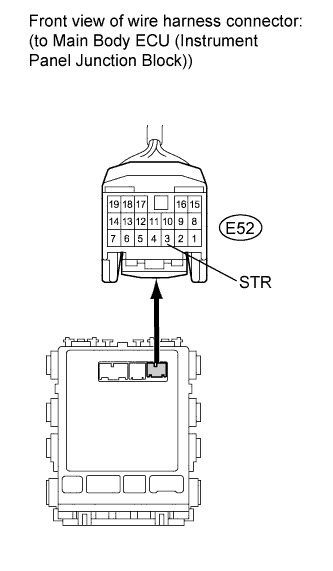
| 14.CHECK HARNESS AND CONNECTOR (MAIN BODY ECU - BODY GROUND) |
Disconnect the E52 connector from the main body ECU (instrument panel junction block).
Measure the resistance according to the value(s) in the table below.
- Standard Resistance:
Tester Connection
| Condition
| Specified Condition
|
E52-3 (STR) - Body ground
| Shift position is P or N
| 105 to 115 Ω
|
E52-3 (STR) - Body ground
| Shift position is not P nor N
| 10 kΩ or higher
|
| OK |
|
|
|
| REPLACE MAIN BODY ECU (INSTRUMENT PANEL JUNCTION BLOCK) |
|
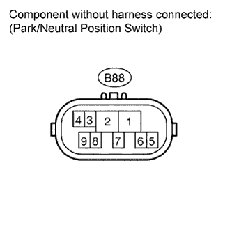
| 15.INSPECT PARK/NEUTRAL POSITION SWITCH |
Disconnect the B88 connector.
Measure the resistance according to the value(s) in the table below.
- Standard Resistance:
Tester Connection
| Condition
| Specified Condition
|
4 - 5
| P
| Below 1 Ω
|
4 - 5
| N
| Below 1 Ω
|
4 - 5
| Except P and N
| 10 kΩ or higher
|
| 16.CHECK HARNESS AND CONNECTOR (MAIN BODY ECU - PARK/NEUTRAL POSITION SWITCH) |
Measure the resistance according to the value(s) in the table below.
- Standard Resistance:
Tester Connection
| Condition
| Specified Condition
|
E52-3 (STR) - B88-4
| Always
| Below 1 Ω
|
E52-3 (STR) or B88-4 - Body ground
| Always
| 10 kΩ or higher
|
| | REPAIR OR REPLACE HARNESS OR CONNECTOR (MAIN BODY ECU - PARK/NEUTRAL POSITION SWITCH) |
|
|
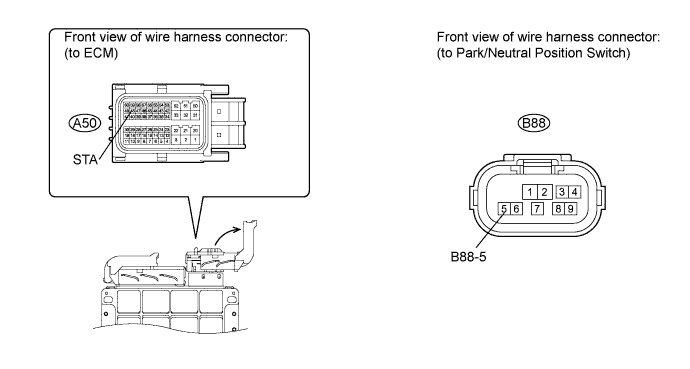
| 17.CHECK HARNESS AND CONNECTOR (PARK/NEUTRAL POSITION SWITCH - ECM) |
Disconnect the E50 connector from the ECM.
Measure the resistance according to the value(s) in the table below.
- Standard Resistance:
Tester Connection
| Condition
| Specified Condition
|
B88-5 - A50-48 (STA)
| Always
| Below 1 Ω
|
B88-5 or A50-48 (STA) - Body ground
| Always
| 10 kΩ or higher
|
| | REPAIR OR REPLACE HARNESS OR CONNECTOR (PARK/NEUTRAL POSITION SWITCH - ECM) |
|
|
Remove the ST relay from engine room relay block.
Measure the resistance according to the value(s) in the table below.
- Standard Resistance:
Tester Connection
| Condition
| Specified Condition
|
3 - 5
| When battery voltage is not applied to terminals 1 and 2
| 10 kΩ or higher
|
3 - 5
| When battery voltage is applied to terminals 1 and 2
| Below 1 Ω
|
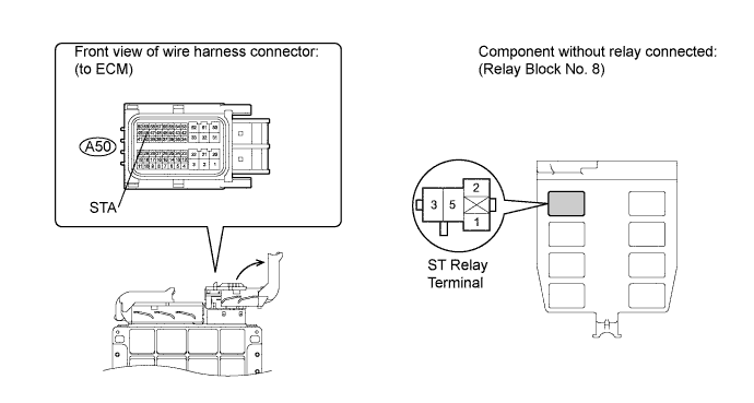
| 19.CHECK HARNESS AND CONNECTOR (ECM - ST RELAY) |
Measure the resistance according to the value(s) in the table below.
- Standard Resistance:
Tester Connection
| Condition
| Specified Condition
|
Relay block No. 8 ST relay terminal 2 - A50-48 (STA)
| Always
| Below 1 Ω
|
Relay block No. 8 ST relay terminal 2 or A50-48 (STA) - Body ground
| Always
| 10 kΩ or higher
|
| | REPAIR OR REPLACE HARNESS OR CONNECTOR (ECM - ST RELAY) |
|
|
| OK |
|
|
|
| REPAIR OR REPLACE HARNESS OR CONNECTOR (ST RELAY - BODY GROUND) |
|
Remove the ST CUT relay from the relay block No. 8.
Measure the resistance according to the value(s) in the table below.
- Standard Resistance:
Tester Connection
| Condition
| Specified Condition
|
3 - 5
| When battery voltage is applied to terminals 1 and 2
| Below 1 Ω
|
3 - 5
| When battery voltage is not applied to terminals 1 and 2
| 10 kΩ or higher
|
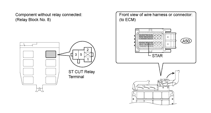
| 21.CHECK HARNESS AND CONNECTOR (ST CUT RELAY - ECM) |
Disconnect the A50 connector from the ECM.
Measure the resistance according to the value(s) in the table below.
- Standard Resistance:
Tester Connection
| Condition
| Specified Condition
|
Relay block No. 8 ST CUT relay terminal 5 - A50-25 (STAR)
| Always
| Below 1 Ω
|
Relay block No. 8 ST CUT relay terminal 5 or A50-25 (STAR) - Body ground
| Always
| 10 kΩ or higher
|
| | REPAIR OR REPLACE HARNESS OR CONNECTOR (ST CUT RELAY - ECM) |
|
|
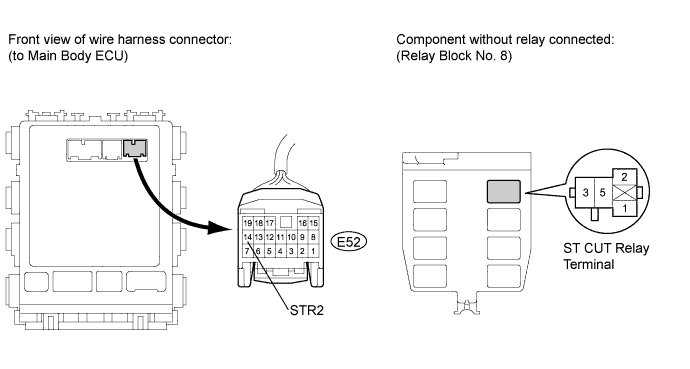
| 22.CHECK HARNESS AND CONNECTOR (ST CUT RELAY - MAIN BODY ECU) |
Disconnect the E52 connector from the main body ECU (instrument panel junction block).
Measure the resistance according to the value(s) in the table below.
- Standard Resistance:
Tester Connection
| Condition
| Specified Condition
|
Relay block No. 8 ST CUT relay terminal 5 - E52-14 (STR2)
| Always
| Below 1 Ω
|
Relay block No. 8 ST CUT relay terminal 5 or E52-14 (STR2) - Body ground
| Always
| 10 kΩ or higher
|
| | REPAIR OR REPLACE HARNESS OR CONNECTOR (ST CUT RELAY - MAIN BODY ECU) |
|
|
| 23.CHECK HARNESS AND CONNECTOR (ECM - ST RELAY) |
Measure the resistance according to the value(s) in the table below.
- Standard Resistance:
Tester Connection
| Condition
| Specified Condition
|
Relay block No. 8 ST relay terminal 2 - A50-48 (STA)
| Always
| Below 1 Ω
|
Relay block No. 8 ST relay terminal 2 or A50-48 (STA) - Body ground
| Always
| 10 kΩ or higher
|
| | REPAIR OR REPLACE HARNESS OR CONNECTOR (ECM - ST RELAY) |
|
|
| 24.REGISTER RECOGNITION CODE (ECU CODE) |
Register the recognition code (ECU code) (COROLLA_ZRE142 RM000000QYF05AX.html).
| 25.CHECK CRANKING FUNCTION |
Check the engine cranking function.
When there is fuel in the fuel tank, the key is inside the vehicle, and the shift lever is in P, check that depressing the brake pedal and pressing the engine switch crank the engine.
- Result:
Result
| Proceed to
|
Engine does not crank
| A
|
Engine cranks
| B
|
| 26.REPLACE CERTIFICATION ECU (SMART KEY ECU ASSEMBLY) |
Replace the certification ECU (smart key ECU assembly) (COROLLA_ZRE142 RM000003G0O004X.html).
Register the key (COROLLA_ZRE142 RM000000QYF05AX_01_0001.html).
| 28.CHECK CRANKING FUNCTION |
Check the engine cranking function.
When there is fuel in the fuel tank, the key is inside the vehicle, and the shift lever is in P, check that depressing the brake pedal and pressing the engine switch crank the engine.
- Result:
Result
| Proceed to
|
Engine does not crank
| A
|
Engine cranks
| B
|
| 29.REGISTER RECOGNITION CODE (ECU CODE) |
Register the recognition code (ECU code) (COROLLA_ZRE142 RM000000QYF05AX.html).
| 30.CHECK CRANKING FUNCTION |
Check the engine cranking function.
When there is fuel in the fuel tank, the key is inside the vehicle, and the shift lever is in P, check that depressing the brake pedal and pressing the engine switch crank the engine.
- Result:
Result
| Proceed to
|
Engine does not crank
| A
|
Engine cranks
| B
|
| 31.REPLACE STEERING LOCK ECU |
Replace the steering lock ECU (COROLLA_ZRE142 RM000000UD005GX_01_0019.html).
| 32.REGISTER RECOGNITION CODE (ECU CODE) |
Register the recognition code (ECU code) (COROLLA_ZRE142 RM000000QYF05AX.html).
| 33.CHECK CRANKING FUNCTION |
Check the engine cranking function.
When there is fuel in the fuel tank, the key is inside the vehicle, and the shift lever is in P, check that depressing the brake pedal and pressing the engine switch crank the engine.
- Result:
Result
| Proceed to
|
Engine does not crank
| A
|
Engine cranks
| B
|
| 34.READ VALUE USING TECHSTREAM (ENGINE START REQUEST) |
Connect Techstream to the DLC3.
- HINT:
- When using Techstream with the engine switch off, turn on and off any of the door courtesy light switches repeatedly at 1.5 second intervals or less until communication between the Techstream and vehicle starts.
Turn the engine switch on (IG).
Read the Data List according to the displays on the Techstream.
Smart KeyTester Display
| Measurement Item/Range
| Normal Condition
| Diagnostic Note
|
Start Rqst
| Start request signal response / OK or NG
| OK: Received
NG: Not received
| -
|
- OK:
- "OK" (received) and "NG" (not received) appear on the screen.