Front Lower Ball Joint Installation
INSTALL FRONT LOWER BALL JOINT
INSTALL FRONT AXLE ASSEMBLY
CONNECT FRONT LOWER SUSPENSION ARM
CONNECT TIE ROD END SUB-ASSEMBLY
INSTALL FRONT DISC
INSTALL FRONT DISC BRAKE CALIPER ASSEMBLY
INSTALL FRONT SPEED SENSOR
INSTALL FRONT AXLE SHAFT NUT (for 2AZ-FE)
INSTALL FRONT AXLE SHAFT NUT (for 2ZR-FE)
INSTALL FRONT WHEEL
INSPECT AND ADJUST FRONT WHEEL ALIGNMENT
CHECK FOR SPEED SENSOR SIGNAL
Front Lower Ball Joint -- Installation |
- HINT:
- Use the same procedure for the LH side and RH side.
- The following procedure listed is for the LH side.
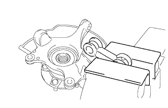
| 1. INSTALL FRONT LOWER BALL JOINT |
Secure the front axle assembly in a vise using aluminum plates.
- NOTICE:
- When using a vise, do not overtighten it.
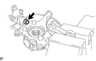
Install the front lower ball joint to the front axle assembly with the nut.
- Torque:
- 2ZR-FE:
- 103 N*m{1050 kgf*cm, 76 ft.*lbf}
- 2AZ-FE:
- 123 N*m{1254 kgf*cm, 91 ft.*lbf}
Install a new cotter pin.
- NOTICE:
- Further tighten the nut up to 60° if the holes for the cotter pin are not aligned.
| 2. INSTALL FRONT AXLE ASSEMBLY |
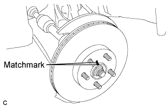
Align the matchmarks and install the front drive shaft assembly to the front axle hub sub-assembly.
Install the front axle assembly to the front shock absorber with the 2 bolts and the 2 nuts.
- Torque:
- 240 N*m{2448 kgf*cm, 176 ft.*lbf}
- NOTICE:
- Be careful not to damage the drive shaft boot or speed sensor rotor.
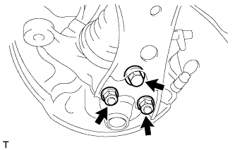
| 3. CONNECT FRONT LOWER SUSPENSION ARM |
Install the front lower suspension arm to the lower ball joint with the bolt and 2 nuts.
- Torque:
- 89 N*m{908 kgf*cm, 66 ft.*lbf}
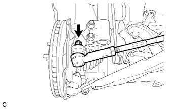
| 4. CONNECT TIE ROD END SUB-ASSEMBLY |
Connect the tie rod end sub-assembly LH to the steering knuckle with the nut.
- Torque:
- 49 N*m{500 kgf*cm, 36 ft.*lbf}
- NOTICE:
- Further tighten the nut up to 60° if the holes for the cotter pin are not aligned.
Install a new cotter pin.
Align the matchmarks of the disc and axle hub, and install the disc.
- NOTICE:
- When replacing the disc with a new one, select the installation position where the front disc has the minimal runout.
| 6. INSTALL FRONT DISC BRAKE CALIPER ASSEMBLY |
Install the front disc brake caliper assembly to the steering knuckle with the 2 bolts.
- Torque:
- 107 N*m{1089 kgf*cm, 79 ft.*lbf}
- NOTICE:
- Do not twist the brake hose when installing the front disc brake caliper assembly.
| 7. INSTALL FRONT SPEED SENSOR |
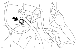
Install the front flexible hose and front speed sensor with the bolt.
- Torque:
- 29 N*m{296 kgf*cm, 21 ft.*lbf}
- NOTICE:
- Install the flexible hose and speed sensor without twisting them.
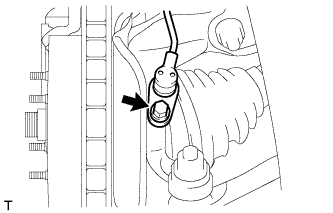
Install the front speed sensor onto the steering knuckle with the bolt.
- Torque:
- 8.5 N*m{87 kgf*cm, 75 in.*lbf}
| 8. INSTALL FRONT AXLE SHAFT NUT (for 2AZ-FE) |
Clean the threaded parts on the drive shaft and axle shaft nut using a non-residue solvent.
- NOTICE:
- Be sure to perform this work for a new drive shaft.
- Keep the threaded parts free of oil and foreign matter.
Using a socket wrench (30 mm), install a new axle shaft nut.
- Torque:
- 216 N*m{2203 kgf*cm, 160 ft.*lbf}
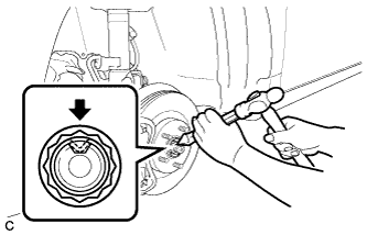
Using a chisel and hammer, caulk the axle shaft nut.
| 9. INSTALL FRONT AXLE SHAFT NUT (for 2ZR-FE) |
Clean the threaded parts on the drive shaft and front axle shaft nut using a non-residue solvent.
- NOTICE:
- Be sure to perform this work for a new drive shaft.
- Keep the threaded parts free of oil and foreign matter.
Using a socket wrench (30 mm), install a new front axle shaft nut.
- Torque:
- 216 N*m{2203 kgf*cm, 160 ft.*lbf}
Using a chisel and hammer, caulk the axle hub nut.
- Torque:
- 103 N*m{1050 kgf*cm, 76 ft.*lbf}
| 11. INSPECT AND ADJUST FRONT WHEEL ALIGNMENT |
- HINT:
- Inspect and adjust front wheel alignment (COROLLA_ZRE142 RM000001Y3B042X.html).
| 12. CHECK FOR SPEED SENSOR SIGNAL |
- HINT:
- Check for speed sensor signal (COROLLA_ZRE142 RM000001JBD052X.html).