Cylinder Block -- Inspection |
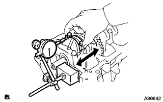
| 1. INSPECT CONNECTING ROD THRUST CLEARANCE |
Install the connecting rod cap (COROLLA_ZRE142 RM00000224E012X.html).
Using a dial indicator, measure the thrust clearance while moving the connecting rod back and forth.
- Standard thrust clearance:
- 0.160 to 0.362 mm (0.00630 to 0.0143 in.)
- Maximum thrust clearance:
- 0.362 mm (0.0143 in.)
 |
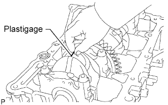
| 2. INSPECT CONNECTING ROD OIL CLEARANCE |
Clean the crank pin and bearing.
Check the crank pin and bearing for pitting and scratches.
Lay a strip of Plastigage on the crank pin.
 |
Check that the front mark of the connecting rod cap is facing forward.
 |
Install the connecting rod cap (COROLLA_ZRE142 RM00000224E012X.html).
- NOTICE:
- Do not turn the crankshaft.
Remove the 2 bolts and connecting rod cap (COROLLA_ZRE142 RM00000224D012X.html).
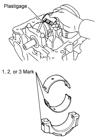
Measure the Plastigage at its widest point.
- Standard oil clearance:
- 0.024 to 0.048 mm (0.000945 to 0.00189 in.)
- Maximum oil clearance:
- 0.063 mm (0.00248 in.)
- NOTICE:
- Completely remove the Plastigage after the measurement.
- HINT:
- If replacing a bearing, replace it with one that has the same number as its respective connecting rod cap. Each bearing's standard thickness is indicated by a 1, 2, or 3 mark on its surface.
- Standard Connecting Rod Large End Bore Diameter:
Mark Specified Condition Mark 1 51.000 to 51.007 mm (2.0079 to 2.0082 in.) Mark 2 51.008 to 51.013 mm (2.0082 to 2.0084 in.) Mark 3 51.014 to 51.020 mm (2.0084 to 2.0087 in.)
- Standard Connecting Rod Bearing Thickness:
Mark Specified Condition Mark 1 1.485 to 1.488 mm (0.0585 to 0.0586 in.) Mark 2 1.489 to 1.491 mm (0.0586 to 0.0587 in.) Mark 3 1.492 to 1.494 mm (0.0587 to 0.0588 in.)
- Standard crankshaft pin diameter:
- 47.990 to 48.000 (1.8894 to 1.8898 in.)
 |
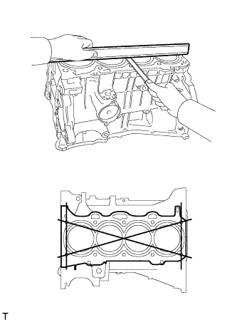
| 3. INSPECT CYLINDER BLOCK FOR WARPAGE |
Using a precision straightedge and feeler gauge, measure the warpage of the surface that contacts the cylinder head gasket.
- Maximum warpage:
- 0.05 mm (0.00197 in.)
 |
| 4. INSPECT CYLINDER BORE |
Using a cylinder gauge, measure the cylinder bore diameter at positions A and B in the thrust and axial directions.
- Standard diameter:
- 88.500 to 88.513 mm (3.4843 to 3.4847 in.)
- Maximum diameter:
- 88.613 mm (3.4887 in.)
 |
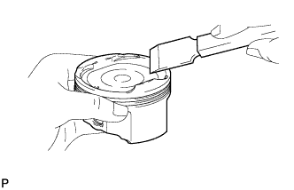
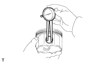
| 5. INSPECT PISTON |
Using a gasket scraper, remove the carbon from the top of the piston.
- NOTICE:
- Do not damage the piston.
 |
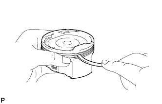
Using a groove cleaning tool or a broken ring, clean the piston ring grooves.
 |
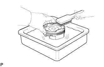
Using a brush and solvent, thoroughly clean the piston.
- NOTICE:
- Do not use a wire brush.
 |
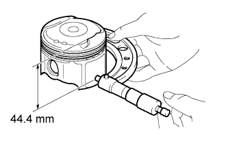
Using a micrometer, measure the piston diameter at right angles to the piston pin hole, and at the piston 44.4 mm (1.748 in.) from the piston head.
- Standard piston diameter:
- 88.469 to 88.479 mm (3.4830 to 3.4834 in.)
 |
| 6. INSPECT PISTON OIL CLEARANCE |
Subtract the piston diameter measurement from the cylinder bore diameter measurement.
- Standard oil clearance:
- 0.021 to 0.044 mm (0.000827 to 0.00173 in.)
- Maximum oil clearance:
- 0.10 mm (0.00394 in.)
| 7. INSPECT RING GROOVE CLEARANCE |
Using a feeler gauge, measure the clearance between a new piston ring and the wall of the ring groove.
- Standard Ring Groove Clearance:
Item Specified Condition No. 1 Ring 0.020 to 0.070 mm (0.000787 to 0.00276 in.) No. 2 Ring 0.020 to 0.060 mm (0.000787 to 0.00236 in.) Oil Ring 0.020 to 0.070 mm (0.000787 to 0.00276 in.)
 |
| 8. INSPECT PISTON RING END GAP |
Using a piston, push the piston ring a little beyond the bottom of the ring travel, 110 mm (4.33 in.) from the top of the cylinder block.
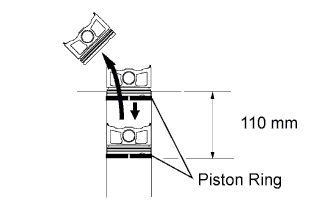 |
Using a feeler gauge, measure the end gap.
- Standard End Gap:
Item Specified Condition No. 1 Ring 0.24 to 0.31 mm (0.00945 to 0.0122 in.) No. 2 Ring 0.33 to 0.43 mm (0.0130 to 0.0169 in.) Oil Ring 0.10 to 0.30 mm (0.00394 to 0.0118 in.)
- Maximum End Gap:
Item Specified Condition No. 1 Ring 0.31 mm (0.0122 in.) No. 2 Ring 0.43 mm (0.0169 in.) Oil Ring 0.30 mm (0.0118 in.)
 |
| 9. INSPECT PISTON PIN OIL CLEARANCE |
Using a caliper gauge, measure the piston pin bore diameter.
- Standard piston pin bore diameter:
- 22.001 to 22.010 mm (0.8662 to 0.8665 in.)
Item Specified Condition A 22.001 to 22.004 mm (0.8662 to 0.8663 in.) B 22.005 to 22.007 mm (0.8663 to 0.8664 in.) C 22.008 to 22.010 mm (0.8665 to 0.8665 in.)
 |
Using a micrometer, measure the piston pin diameter.
- Standard piston pin diameter:
- 21.997 to 22.006 mm (0.8660 to 0.8664 in.)
Item Specified Condition A 21.997 to 22.000 mm (0.8660 to 0.8661 in.) B 22.001 to 22.003 mm (0.8662 to 0.8663 in.) C 22.004 to 22.006 mm (0.8663 to 0.8664 in.)
 |
Using a caliper gauge, measure the connecting rod small end bore diameter.
- Standard connecting rod small end bore diameter:
- 22.005 to 22.014 mm (0.8663 to 0.8667 in.)
Item Specified Condition A 22.005 to 22.008 mm (0.8663 to 0.8665 in.) B 22.009 to 22.011 mm (0.8665 to 0.8666 in.) C 22.012 to 22.014 mm (0.8666 to 0.8667 in.)
 |
Subtract the piston pin diameter measurement from the piston pin bore diameter measurement.
- Standard oil clearance:
- 0.001 to 0.007 mm (0.00004 to 0.0003 in.)
- Maximum oil clearance:
- 0.010 mm (0.0004 in.)
 |
Subtract the piston pin diameter measurement from the connecting rod small end bore diameter measurement.
- Standard oil clearance:
- 0.005 to 0.011 mm (0.0002 to 0.0004 in.)
- Maximum oil clearance:
- 0.011 mm (0.0004 in.)
| 10. INSPECT CONNECTING ROD BOLT |
Using a vernier caliper, measure the tension portion diameter of the bolt.
- Standard diameter:
- 7.2 to 7.3 mm (0.283 to 0.287 in.)
- Minimum diameter:
- 7.0 mm (0.276 in.)
 |
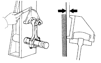
| 11. INSPECT CONNECTING ROD SUB-ASSEMBLY |
Using a connecting rod aligner and feeler gauge, check the connecting rod alignment.
Check for misalignment.
- Maximum misalignment:
- 0.05 mm (0.0020 in.) per 100 mm (3.94 in.)
Check for twist.
- Maximum twist:
- 0.05 mm (0.0020 in.) per 100 mm (3.94 in.)

 |
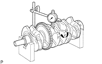
| 12. INSPECT CRANKSHAFT |
Using a dial indicator and V-blocks, measure the circle runout as shown in the illustration.
- Maximum circle runout:
- 0.03 mm (0.0012 in.)
 |
Using a micrometer, measure the diameter of each main journal.
- Standard diameter:
- 54.988 to 55.000 mm (2.1649 to 2.1654 in.)
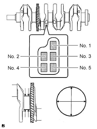 |
Check each main journal for taper and distortion as shown in the illustration.
- Maximum taper and distortion:
- 0.003 mm (0.0001 in.)
- Standard Diameter (Reference):
Mark Specified Condition 0 54.999 to 55.000 mm (2.16531 to 2.16535 in.) 1 54.997 to 54.998 mm (2.16523 to 2.16527 in.) 2 54.995 to 54.996 mm (2.16515 to 2.16519 in.) 3 54.993 to 54.994 mm (2.16507 to 2.16511 in.) 4 54.991 to 54.992 mm (2.16500 to 2.16503 in.) 5 54.988 to 54.990 mm (2.1649 to 2.1650 in.)
Using a micrometer, measure the diameter of each crank pin.
- Standard diameter:
- 47.990 to 48.000 mm (1.8894 to 1.8898 in.)
 |
Inspect each crank pin for taper and distortion as shown in the illustration.
- Maximum taper and distortion:
- 0.003 mm (0.000118 in.)
| 13. INSPECT CRANKSHAFT THRUST CLEARANCE |
Install the main bearing cap (COROLLA_ZRE142 RM00000224E012X.html).
Using a dial indicator, measure the thrust clearance while prying the crankshaft back and forth with a screwdriver.
- Standard thrust clearance:
- 0.04 to 0.24 mm (0.00157 to 0.00945 in.)
- Maximum thrust clearance:
- 0.30 mm (0.0118 in.)
- HINT:
- The thrust washer thickness is 1.93 to 1.98 mm (0.0760 to 0.0780 in.).
 |
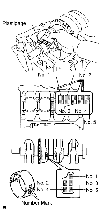
| 14. INSPECT CRANKSHAFT OIL CLEARANCE |
Check the crank journal and bearing for pitting and scratches.
Install the crankshaft bearing (COROLLA_ZRE142 RM00000224E012X.html).
Place the crankshaft on the cylinder block.
Lay a strip of Plastigage across each journal.
 |
Examine the front marks and numbers and install the bearing caps on the cylinder block.
- HINT:
- A number is marked on each main bearing cap to indicate the installation position.
Install the main bearing caps (COROLLA_ZRE142 RM00000224E012X.html).
- NOTICE:
- Do not turn the crankshaft.
Remove the main bearing caps (COROLLA_ZRE142 RM00000224D012X_01_0009.html).
Measure the Plastigage at its widest point.
- Standard oil clearance:
- 0.017 to 0.040 mm (0.000669 to 0.00157 in.)
- Maximum oil clearance:
- 0.060 mm (0.00236 in.)
- NOTICE:
- Remove the Plastigage completely after the measurement.
- HINT:
- If replacing a bearing, select a new one with the same number. If the number of the bearing cannot be determined, calculate the correct bearing number by adding together the numbers imprinted on the cylinder block and crankshaft. Then select a new bearing with the calculated number. There are 4 sizes of standard bearings, marked "1", "2", "3" and "4" accordingly.
- EXAMPLE: Cylinder block "3" + Crankshaft "5" = Total number 8 (Use bearing "3")
Cylinder block + Crankshaft 0 to 2 3 to 5 6 to 8 9 to 11 Bearing to be used "1" "2" "3" "4" - Standard Cylinder Block Journal Bore Diameter:
Mark Specified Condition 0 59.000 to 59.002 mm (2.32283 to 2.32291 in.) 1 59.003 to 59.004 mm (2.32295 to 2.32299 in.) 2 59.005 to 59.006 mm (2.32303 to 2.32307 in.) 3 59.007 to 59.009 mm (2.32311 to 2.32318 in.) 4 59.010 to 59.011 mm (2.32322 to 2.32326 in.) 5 59.012 to 59.013 mm (2.32330 to 2.32334 in.) 6 59.014 to 59.016 mm (2.32338 to 2.32346 in.)
- Standard Crankshaft Journal Diameter:
Mark Specified Condition 0 54.999 to 55.000 mm (2.16531 to 2.16535 in.) 1 54.997 to 54.998 mm (2.16523 to 2.16527 in.) 2 54.995 to 54.996 mm (2.16515 to 2.16519 in.) 3 54.993 to 54.994 mm (2.16507 to 2.16511 in.) 4 54.991 to 54.992 mm (2.16500 to 2.16504 in.) 5 54.988 to 54.990 mm (2.16488 to 2.16496 in.)
- Standard Bearing Center Wall Thickness:
Mark Specified Condition 1 1.993 to 1.996 mm (0.078464 to 0.078583 in.) 2 1.997 to 1.999 mm (0.078622 to 0.078701 in.) 3 2.000 to 2.002 mm (0.078740 to 0.078819 in.) 4 2.003 to 2.005 mm (0.078858 to 0.078937 in.)
 |
| 15. INSPECT CRANKSHAFT BEARING CAP SET RING PIN |
Using a vernier caliper, measure the tension portion diameter of the bolts.
- Standard diameter:
- 7.5 to 7.6 mm (0.295 to 0.299 in.)
- Minimum diameter:
- 7.5 mm (0.295 in.)
 |