DESCRIPTION
WIRING DIAGRAM
INSPECTION PROCEDURE
CHECK PRESENT DTC
CHECK PAST DTC
CHECK CONNECTION OF CONNECTORS
CHECK CONNECTORS
CHECK WIRE HARNESS (OPEN)
CHECK WIRE HARNESS (SHORT)
CHECK WIRE HARNESS (SHORT TO B+)
CHECK WIRE HARNESS (SHORT TO GROUND)
CHECK SIDE AIRBAG SENSOR (DRIVER SIDE)
CHECK CONNECTION OF CONNECTOR
CHECK CONNECTOR
CHECK WIRE HARNESS (OPEN)
CHECK WIRE HARNESS (SHORT)
CHECK WIRE HARNESS (SHORT TO B+)
CHECK WIRE HARNESS (SHORT TO GROUND)
CHECK REAR AIRBAG SENSOR (DRIVER SIDE)
CHECK CENTER AIRBAG SENSOR ASSEMBLY
CHECK CONNECTION OF CONNECTORS
CHECK CONNECTORS
CHECK WIRE HARNESS (OPEN)
CHECK WIRE HARNESS (SHORT)
CHECK WIRE HARNESS (SHORT TO B+)
CHECK WIRE HARNESS (SHORT TO GROUND)
CHECK SIDE AIRBAG SENSOR (DRIVER SIDE)
CHECK CENTER AIRBAG SENSOR ASSEMBLY
DTC B1622/81 Lost Communication with Driver Side - Side Airbag Sensor Assembly |
DTC B1623/81 Driver Side - Side Airbag Sensor Assembly Initialization Incomplete |
DTC B1632/81 Lost Communication with Driver Side Rear Airbag Sensor |
DTC B1633/81 Driver Side Rear Airbag Sensor Initialization Incomplete |
DTC B1642/81 Lost Communication with Driver Side Satellite Sensor Bus |
DTC B1643/81 Driver Side Satellite Sensor Bus Initialization Incomplete |
DESCRIPTION
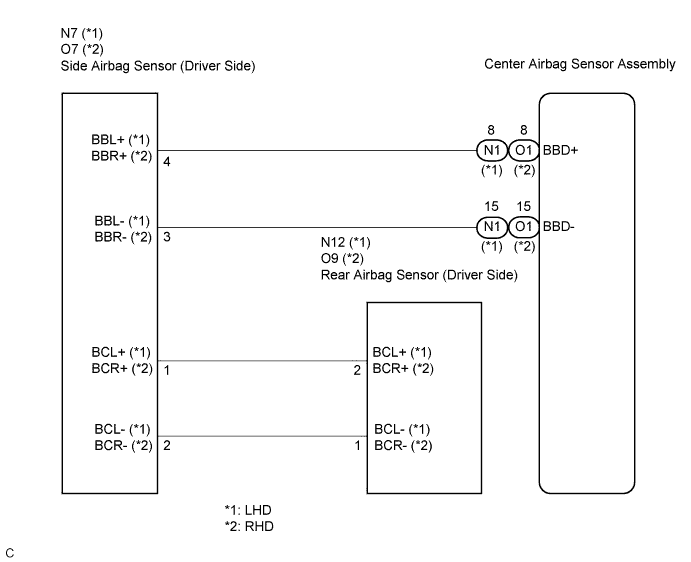
The circuit for the driver side - side collision sensor (to determine deployment of the front seat side airbag assembly (driver side) and curtain shield airbag assembly (driver side)) is composed of the center airbag sensor assembly, side airbag sensor (driver side), and rear airbag sensor (driver side).The side airbag sensor (driver side) and rear airbag sensor (driver side) detect impacts to the vehicle and send signals to the center airbag sensor assembly to determine if the airbag should be deployed.DTC B1622/81, B1623/81, B1632/81, B1633/81, B1642/81, or B1643/81 is recorded when a malfunction is detected in the circuit for the driver side - side collision sensor (to determine deployment of the front seat side airbag assembly (driver side) and curtain shield airbag assembly (driver side)).DTC No.
| DTC Detecting Condition
| Trouble Area
|
1622/81
1623/81
1632/81
1633/81
1642/81
1643/81
| - The center airbag sensor assembly receives a line short circuit signal, an open circuit signal, a short circuit to ground signal or a short circuit to B+ signal in the circuit for the driver side - side collision (to determine deployment of the front seat side airbag assembly (driver side) and curtain shield airbag assembly (driver side)) for 2 seconds.
- Side airbag sensor (driver side) malfunction
- Rear airbag sensor (driver side) malfunction
- Center airbag sensor assembly malfunction
| - Floor wire (for LHD)
- Floor wire No. 2 (for RHD)
- Side airbag sensor (Driver side)
- Rear airbag sensor (Driver side)
- Center airbag sensor assembly
|
WIRING DIAGRAM
INSPECTION PROCEDURE
Turn the ignition switch to the ON position, and wait for at least 60 seconds.
Turn the ignition switch to the LOCK position.
- HINT:
- If a communication error occurs, DTCs for both the driver and passenger sides will be stored simultaneously. To identify the malfunctioning area, turn the ignition switch to the LOCK position and then ON position again.
Turn the ignition switch to the ON position, and wait for at least 60 seconds.
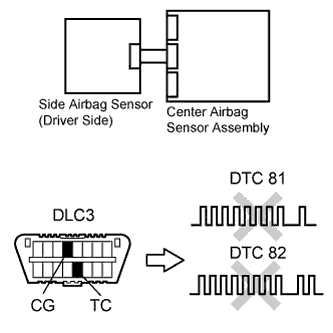
Check the present DTCs (CAMRY_ACV40 RM000000XFE0BNX.html).
- Result:
Result
| Proceed to
|
Present DTC B1623, B1633, B1643, or 81 is output.
| A
|
Present DTC B1628, B1638, B1648, or 82 is output.
| B
|
Present DTC B1623, B1633, B1643, or 81 and B1628, B1638, B1648, or 82 are not output.
| C
|
- HINT:
- DTCs indicating communication errors will be changed to DTCs indicating errors in initialization by turning the ignition switch to the LOCK position and then ON position again.
- Codes other than present DTC B1623, B1633, B1643, or 81 and B1628, B1638, B1648, or 82 may be output at this time, but they are not related to this check.
| | REPAIR CIRCUITS INDICATED BY OUTPUT DTCS |
|
|
| |
|
Check the past DTCs (CAMRY_ACV40 RM000000XFE0BNX.html).
- Result:
Result
| Proceed to
|
- Past DTC B1632, B1642, or 81 is output.
- Past DTC B1622, B1632, B1642, or 81 is not output.
| A
|
Past DTC B1622 is output.
| B
|
- HINT:
- Codes other than past DTC B1622, B1632, B1642, or 81 may be output at this time, but they are not related to this check.
| 3.CHECK CONNECTION OF CONNECTORS |
Turn the ignition switch to the LOCK position.
Disconnect the negative (-) terminal cable from the battery, and wait for at least 90 seconds.
Check that the connectors are properly connected to the center airbag sensor assembly and the side airbag sensor (driver side).
- OK:
- The connectors are properly connected.
| | CONNECT CONNECTORS PROPERLY |
|
|
Disconnect the connectors from the center airbag sensor assembly and side airbag sensor (driver side).
Check that the connectors (on the center airbag sensor assembly side and side airbag sensor (driver side) side) are not damaged.
- OK:
- The connectors are not deformed or damaged.
- Result:
Result
| Proceed to
|
OK
| A
|
NG (for LHD)
| B
|
NG (for RHD)
| C
|
| | REPAIR OR REPLACE FLOOR WIRE |
|
|
| | REPAIR OR REPLACE FLOOR WIRE NO. 2 |
|
|
| 5.CHECK WIRE HARNESS (OPEN) |
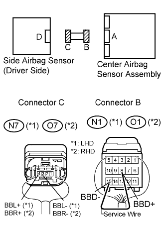
Using a service wire, connect terminals 8 (BBD+) and 15 (BBD-) of connector B.
- NOTICE:
- Do not forcibly insert a service wire into the terminals of the connector when connecting.
Measure the resistance according to the value(s) in the table below.
- Standard resistance:
- for LHD:
Tester connection
| Condition
| Specified condition
|
N7-4 (BBL+) - N7-3 (BBL-)
| Always
| Below 1 Ω
|
- for RHD:
Tester connection
| Condition
| Specified condition
|
O7-4 (BBR+) - O7-3 (BBR-)
| Always
| Below 1 Ω
|
- Result:
Result
| Proceed to
|
OK
| A
|
NG (for LHD)
| B
|
NG (for RHD)
| C
|
| | REPAIR OR REPLACE FLOOR WIRE |
|
|
| | REPAIR OR REPLACE FLOOR WIRE NO. 2 |
|
|
| 6.CHECK WIRE HARNESS (SHORT) |
Disconnect the service wire from connector B.
Measure the resistance according to the value(s) in the table below.
- Standard resistance:
- for LHD:
Tester connection
| Condition
| Specified condition
|
N7-4 (BBL+) - N7-3 (BBL-)
| Always
| 1 MΩ or higher
|
- for RHD:
Tester connection
| Condition
| Specified condition
|
O7-4 (BBR+) - O7-3 (BBR-)
| Always
| 1 MΩ or higher
|
- Result:
Result
| Proceed to
|
OK
| A
|
NG (for LHD)
| B
|
NG (for RHD)
| C
|
| | REPAIR OR REPLACE FLOOR WIRE |
|
|
| | REPAIR OR REPLACE FLOOR WIRE NO. 2 |
|
|
| 7.CHECK WIRE HARNESS (SHORT TO B+) |
Connect the negative (-) terminal cable to the battery, and wait for at least 2 seconds.
Turn the ignition switch to the ON position.
Measure the voltage according to the value(s) in the table below.
- Standard voltage:
- for LHD:
Tester connection
| Condition
| Specified condition
|
N7-4 (BBL+) - Body ground
| Ignition switch ON
| Below 1 V
|
N7-3 (BBL-) - Body ground
| Ignition switch ON
| Below 1 V
|
- for RHD:
Tester connection
| Condition
| Specified condition
|
O7-4 (BBR+) - Body ground
| Ignition switch ON
| Below 1 V
|
O7-3 (BBR-) - Body ground
| Ignition switch ON
| Below 1 V
|
- Result:
Result
| Proceed to
|
OK
| A
|
NG (for LHD)
| B
|
NG (for RHD)
| C
|
| | REPAIR OR REPLACE FLOOR WIRE |
|
|
| | REPAIR OR REPLACE FLOOR WIRE NO. 2 |
|
|
| 8.CHECK WIRE HARNESS (SHORT TO GROUND) |
Turn the ignition switch to the LOCK position.
Disconnect the negative (-) terminal cable from the battery, and wait for at least 90 seconds.
Measure the resistance according to the value(s) in the table below.
- Standard resistance:
- for LHD:
Tester connection
| Condition
| Specified condition
|
N7-4 (BBL+) - Body ground
| Always
| 1 MΩ or higher
|
N7-3 (BBL-) - Body ground
| Always
| 1 MΩ or higher
|
- for RHD:
Tester connection
| Condition
| Specified condition
|
O7-4 (BBR+) - Body ground
| Always
| 1 MΩ or higher
|
O7-3 (BBR-) - Body ground
| Always
| 1 MΩ or higher
|
- Result:
Result
| Proceed to
|
OK
| A
|
NG (for LHD)
| B
|
NG (for RHD)
| C
|
| | REPAIR OR REPLACE FLOOR WIRE |
|
|
| | REPAIR OR REPLACE FLOOR WIRE NO. 2 |
|
|
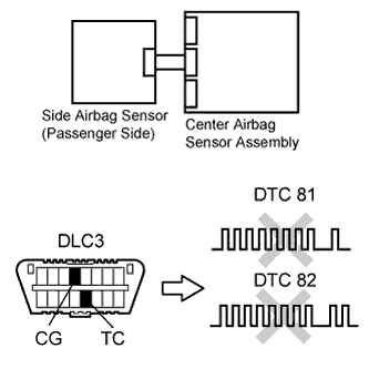
| 9.CHECK SIDE AIRBAG SENSOR (DRIVER SIDE) |
Connect the connector to the center airbag sensor assembly.
Interchange the side airbag sensor (passenger side) with side airbag sensor (driver side) and connect the connectors to them.
Connect the negative (-) terminal cable to the battery, and wait for at least 2 seconds.
Turn the ignition switch to the ON position, and wait for at least 60 seconds.
Clear the DTCs stored in the memory (CAMRY_ACV40 RM000000XFE0BNX.html).
Turn the ignition switch to the LOCK position.
Turn the ignition switch to the ON position, and wait for at least 60 seconds.
Check the DTCs (CAMRY_ACV40 RM000000XFE0BNX.html).
- Result:
Result
| Proceed to
|
DTC B1623, B1633, B1643, or 81 is output.
| A
|
DTC B1628, B1638, B1648, or 82 is output.
| B
|
DTC B1623, B1633, B1643, or 81 and B1628, B1638, B1648, or 82 are not output.
| C
|
| 10.CHECK CONNECTION OF CONNECTOR |
Turn the ignition switch to the LOCK position.
Disconnect the negative (-) terminal cable from the battery, and wait for at least 90 seconds.
Return the side airbag sensor (passenger side) and side airbag sensor (driver side) to their original positions and connect the connectors to them.
Check that the connector is properly connected to the rear airbag sensor (driver side).
- OK:
- The connector is properly connected.
| | CONNECT CONNECTOR PROPERLY |
|
|
Disconnect the connectors from the side airbag sensor (driver side) and rear airbag sensor (driver side).
Check that the connector (on the rear airbag sensor (driver side) side) is not damaged.
- OK:
- The connector is not deformed or damaged.
- Result:
Result
| Proceed to
|
OK
| A
|
NG (for LHD)
| B
|
NG (for RHD)
| C
|
| | REPAIR OR REPLACE FLOOR WIRE |
|
|
| | REPAIR OR REPLACE FLOOR WIRE NO. 2 |
|
|
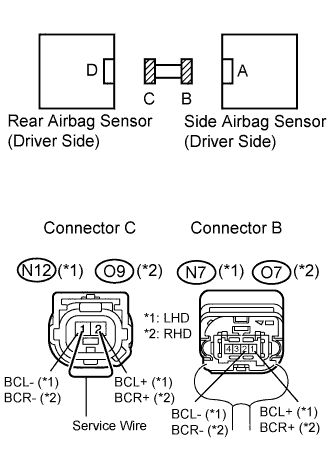
| 12.CHECK WIRE HARNESS (OPEN) |
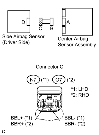
Using a service wire, connect terminals 2 (BCL+) and 1 (BCL-) of connector C.
- NOTICE:
- Do not forcibly insert a service wire into the terminals of the connector when connecting.
Measure the resistance according to the value(s) in the table below.
- Standard resistance:
- for LHD:
Tester connection
| Condition
| Specified condition
|
N7-1 (BCL+) - N7-2 (BCL-)
| Always
| Below 1 Ω
|
- for RHD:
Tester connection
| Condition
| Specified condition
|
O7-1 (BCR+) - O7-2 (BCR-)
| Always
| Below 1 Ω
|
- Result:
Result
| Proceed to
|
OK
| A
|
NG (for LHD)
| B
|
NG (for RHD)
| C
|
| | REPAIR OR REPLACE FLOOR WIRE |
|
|
| | REPAIR OR REPLACE FLOOR WIRE NO. 2 |
|
|
| 13.CHECK WIRE HARNESS (SHORT) |
Disconnect the service wire from connector C.
Measure the resistance according to the value(s) in the table below.
- Standard resistance:
- for LHD:
Tester connection
| Condition
| Specified condition
|
N7-1 (BCL+) - N7-2 (BCL-)
| Always
| 1 MΩ or higher
|
- for RHD:
Tester connection
| Condition
| Specified condition
|
O7-1 (BCR+) - O7-2 (BCR-)
| Always
| 1 MΩ or higher
|
- Result:
Result
| Proceed to
|
OK
| A
|
NG (for LHD)
| B
|
NG (for RHD)
| C
|
| | REPAIR OR REPLACE FLOOR WIRE |
|
|
| | REPAIR OR REPLACE FLOOR WIRE NO. 2 |
|
|
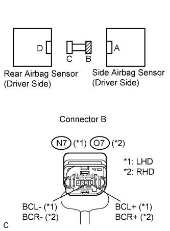
| 14.CHECK WIRE HARNESS (SHORT TO B+) |
Connect the negative (-) terminal cable to the battery, and wait for at least 2 seconds.
Turn the ignition switch to the ON position.
Measure the voltage according to the value(s) in the table below.
- Standard voltage:
- for LHD:
Tester connection
| Condition
| Specified condition
|
N7-1 (BCL+) - Body ground
| Ignition switch ON
| Below 1 V
|
N7-2 (BCL-) - Body ground
| Ignition switch ON
| Below 1 V
|
- for RHD:
Tester connection
| Condition
| Specified condition
|
O7-1 (BCR+) - Body ground
| Ignition switch ON
| Below 1 V
|
O7-2 (BCR-) - Body ground
| Ignition switch ON
| Below 1 V
|
- Result:
Result
| Proceed to
|
OK
| A
|
NG (for LHD)
| B
|
NG (for RHD)
| C
|
| | REPAIR OR REPLACE FLOOR WIRE |
|
|
| | REPAIR OR REPLACE FLOOR WIRE NO. 2 |
|
|
| 15.CHECK WIRE HARNESS (SHORT TO GROUND) |
Turn the ignition switch to the LOCK position.
Disconnect the negative (-) terminal cable from the battery, and wait for at least 90 seconds.
Measure the resistance according to the value(s) in the table below.
- Standard resistance:
- for LHD:
Tester connection
| Condition
| Specified condition
|
N7-1 (BCL+) - Body ground
| Always
| 1 MΩ or higher
|
N7-2 (BCL-) - Body ground
| Always
| 1 MΩ or higher
|
- for RHD:
Tester connection
| Condition
| Specified condition
|
O7-1 (BCR+) - Body ground
| Always
| 1 MΩ or higher
|
O7-2 (BCR-) - Body ground
| Always
| 1 MΩ or higher
|
- Result:
Result
| Proceed to
|
OK
| A
|
NG (for LHD)
| B
|
NG (for RHD)
| C
|
| | REPAIR OR REPLACE FLOOR WIRE |
|
|
| | REPAIR OR REPLACE FLOOR WIRE NO. 2 |
|
|
| 16.CHECK REAR AIRBAG SENSOR (DRIVER SIDE) |
Connect the connector to the side airbag sensor (driver side).
Interchange the rear airbag sensor (passenger side) with rear airbag sensor (driver side) and connect the connectors to them.
Connect the negative (-) terminal cable to the battery, and wait for at least 2 seconds.
Turn the ignition switch to the ON position, and wait for at least 60 seconds.
Clear the DTCs stored in the memory (CAMRY_ACV40 RM000000XFE0BNX.html).
Turn the ignition switch to the LOCK position.
Turn the ignition switch to the ON position, and wait for at least 60 seconds.
Check the DTCs (CAMRY_ACV40 RM000000XFE0BNX.html).
- Result:
Result
| Proceed to
|
DTC B1623, B1633, B1643, or 81 is output.
| A
|
DTC B1628, B1638, B1648, or 82 is output.
| B
|
DTC B1623, B1633, B1643, or 81 and B1628, B1638, B1648, or 82 are not output.
| C
|
- HINT:
- Codes other than DTC B1623, B1633, B1643, or 81 and B1628, B1638, B1648, or 82 may be output at this time, but they are not related to this check.
| 17.CHECK CENTER AIRBAG SENSOR ASSEMBLY |
Turn the ignition switch to the LOCK position.
Disconnect the negative (-) terminal cable from the battery, and wait for at least 90 seconds.
Return the rear airbag sensor (passenger side) and rear airbag sensor (driver side) to their original positions and connect the connectors to them.
Connect the negative (-) terminal cable to the battery, and wait for at least 2 seconds.
Turn the ignition switch to the ON position, and wait for at least 60 seconds.
Clear the DTCs stored in the memory (CAMRY_ACV40 RM000000XFE0BNX.html).
Turn the ignition switch to the LOCK position.
Turn the ignition switch to the ON position, and wait for at least 60 seconds.
Check the DTCs (CAMRY_ACV40 RM000000XFE0BNX.html).
- OK:
- DTC B1623, B1633, B1643, or 81 is not output.
- HINT:
- Codes other than DTC B1623, B1633, B1643, or 81 may be output at this time, but they are not related to this check.
| 18.CHECK CONNECTION OF CONNECTORS |
Turn the ignition switch to the LOCK position.
Disconnect the negative (-) terminal cable from the battery, and wait for at least 90 seconds.
Check that the connectors are properly connected to the center airbag sensor assembly and the side airbag sensor (driver side).
- OK:
- The connectors are properly connected.
| | CONNECT CONNECTORS PROPERLY |
|
|
Disconnect the connectors from the center airbag sensor assembly and side airbag sensor (driver side).
Check that the connectors (on the center airbag sensor assembly side and side airbag sensor (driver side) side) are not damaged.
- OK:
- The connectors are not deformed or damaged.
- Result:
Result
| Proceed to
|
OK
| A
|
NG (for LHD)
| B
|
NG (for RHD)
| C
|
| | REPAIR OR REPLACE FLOOR WIRE |
|
|
| | REPAIR OR REPLACE FLOOR WIRE NO. 2 |
|
|
| 20.CHECK WIRE HARNESS (OPEN) |
Using a service wire, connect terminals 8 (BBD+) and 15 (BBD-) of connector B.
- NOTICE:
- Do not forcibly insert a service wire into the terminals of the connector when connecting.
Measure the resistance according to the value(s) in the table below.
- Standard resistance:
- for LHD:
Tester connection
| Condition
| Specified condition
|
N7-4 (BBL+) - N7-3 (BBL-)
| Always
| Below 1 Ω
|
- for RHD:
Tester connection
| Condition
| Specified condition
|
O7-4 (BBR+) - O7-3 (BBR-)
| Always
| Below 1 Ω
|
- Result:
Result
| Proceed to
|
OK
| A
|
NG (for LHD)
| B
|
NG (for RHD)
| C
|
| | REPAIR OR REPLACE FLOOR WIRE |
|
|
| | REPAIR OR REPLACE FLOOR WIRE NO. 2 |
|
|
| 21.CHECK WIRE HARNESS (SHORT) |
Disconnect the service wire from connector B.
Measure the resistance according to the value(s) in the table below.
- Standard resistance:
- for LHD:
Tester connection
| Condition
| Specified condition
|
N7-4 (BBL+) - N7-3 (BBL-)
| Always
| 1 MΩ or higher
|
- for RHD:
Tester connection
| Condition
| Specified condition
|
O7-4 (BBR+) - O7-3 (BBR-)
| Always
| 1 MΩ or higher
|
- Result:
Result
| Proceed to
|
OK
| A
|
NG (for LHD)
| B
|
NG (for RHD)
| C
|
| | REPAIR OR REPLACE FLOOR WIRE |
|
|
| | REPAIR OR REPLACE FLOOR WIRE NO. 2 |
|
|
| 22.CHECK WIRE HARNESS (SHORT TO B+) |
Connect the negative (-) terminal cable to the battery, and wait for at least 2 seconds.
Turn the ignition switch to the ON position.
Measure the voltage according to the value(s) in the table below.
- Standard voltage:
- for LHD:
Tester connection
| Condition
| Specified condition
|
N7-4 (BBL+) - Body ground
| Ignition switch ON
| Below 1 V
|
N7-3 (BBL-) - Body ground
| Ignition switch ON
| Below 1 V
|
- for RHD:
Tester connection
| Condition
| Specified condition
|
O7-4 (BBR+) - Body ground
| Ignition switch ON
| Below 1 V
|
O7-3 (BBR-) - Body ground
| Ignition switch ON
| Below 1 V
|
- Result:
Result
| Proceed to
|
OK
| A
|
NG (for LHD)
| B
|
NG (for RHD)
| C
|
| | REPAIR OR REPLACE FLOOR WIRE |
|
|
| | REPAIR OR REPLACE FLOOR WIRE NO. 2 |
|
|
| 23.CHECK WIRE HARNESS (SHORT TO GROUND) |
Turn the ignition switch to the LOCK position.
Disconnect the negative (-) terminal cable from the battery, and wait for at least 90 seconds.
Measure the resistance according to the value(s) in the table below.
- Standard resistance:
- for LHD:
Tester connection
| Condition
| Specified condition
|
N7-4 (BBL+) - Body ground
| Always
| 1 MΩ or higher
|
N7-3 (BBL-) - Body ground
| Always
| 1 MΩ or higher
|
- for RHD:
Tester connection
| Condition
| Specified condition
|
O7-4 (BBR+) - Body ground
| Always
| 1 MΩ or higher
|
O7-3 (BBR-) - Body ground
| Always
| 1 MΩ or higher
|
- Result:
Result
| Proceed to
|
OK
| A
|
NG (for LHD)
| B
|
NG (for RHD)
| C
|
| | REPAIR OR REPLACE FLOOR WIRE |
|
|
| | REPAIR OR REPLACE FLOOR WIRE NO. 2 |
|
|
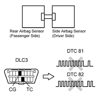
| 24.CHECK SIDE AIRBAG SENSOR (DRIVER SIDE) |
Connect the connector to the center airbag sensor assembly.
Interchange the side airbag sensor (passenger side) with side airbag sensor (driver side) and connect the connectors to them.
Connect the negative (-) terminal cable to the battery, and wait for at least 2 seconds.
Turn the ignition switch to the ON position, and wait for at least 60 seconds.
Clear the DTCs stored in the memory (CAMRY_ACV40 RM000000XFE0BNX.html).
Turn the ignition switch to the LOCK position.
Turn the ignition switch to the ON position, and wait for at least 60 seconds.
Check the DTCs (CAMRY_ACV40 RM000000XFE0BNX.html).
- Result:
Result
| Proceed to
|
DTC B1623, B1633, B1643, or 81 is output.
| A
|
DTC B1628, B1638, B1648, or 82 is output.
| B
|
DTC B1623, B1633, B1643, or 81 and B1628, B1638, B1648, or 82 are not output.
| C
|
| 25.CHECK CENTER AIRBAG SENSOR ASSEMBLY |
Turn the ignition switch to the LOCK position.
Disconnect the negative (-) terminal cable from the battery, and wait for at least 90 seconds.
Return the side airbag sensor (passenger side) and side airbag sensor (driver side) to their original positions and connect the connectors to them.
Connect the negative (-) terminal cable to the battery, and wait for at least 2 seconds.
Turn the ignition switch to the ON position, and wait for at least 60 seconds.
Clear the DTCs stored in the memory (CAMRY_ACV40 RM000000XFE0BNX.html).
Turn the ignition switch to the LOCK position.
Turn the ignition switch to the ON position, and wait for at least 60 seconds.
Check the DTCs (CAMRY_ACV40 RM000000XFE0BNX.html).
- OK:
- DTC B1623, B1633, B1643, or 81 is not output.
- HINT:
- Codes other than DTC B1623, B1633, B1643, or 81 may be output at this time, but they are not related to this check.