Center Airbag Sensor Assembly Removal
PRECAUTION
DISCONNECT CABLE FROM NEGATIVE BATTERY TERMINAL
REMOVE SHIFT LEVER KNOB SUB-ASSEMBLY (for Automatic Transaxle)
REMOVE SHIFT LEVER KNOB SUB-ASSEMBLY (for Manual Transaxle)
REMOVE NO. 1 INSTRUMENT CLUSTER FINISH PANEL GARNISH
REMOVE NO. 2 INSTRUMENT CLUSTER FINISH PANEL GARNISH
REMOVE FLOOR SHIFT POSITION INDICATOR HOUSING SUB-ASSEMBLY (for Automatic Transaxle)
REMOVE UPPER CONSOLE PANEL (for Manual Transaxle)
REMOVE UPPER CONSOLE REAR PANEL SUB-ASSEMBLY (for Automatic Transaxle)
REMOVE UPPER CONSOLE REAR PANEL SUB-ASSEMBLY (for Manual Transaxle)
REMOVE UPPER CONSOLE PANEL SUB-ASSEMBLY
REMOVE FRONT DOOR SCUFF PLATE LH
REMOVE COWL SIDE TRIM SUB-ASSEMBLY LH
REMOVE LOWER INSTRUMENT PANEL FINISH PANEL LH
REMOVE FRONT DOOR SCUFF PLATE RH
REMOVE COWL SIDE TRIM SUB-ASSEMBLY RH
REMOVE INSTRUMENT PANEL NO. 2 UNDER COVER SUB-ASSEMBLY
REMOVE LOWER INSTRUMENT PANEL SUB-ASSEMBLY
REMOVE CONSOLE BOX POCKET
REMOVE CONSOLE BOX CARPET
REMOVE CONSOLE BOX ASSEMBLY
REMOVE NO. 1 CONSOLE BOX INSERT FRONT
REMOVE NO. 2 CONSOLE BOX INSERT FRONT
REMOVE NO. 1 CONSOLE BOX DUCT (w/ Rear Register Duct)
REMOVE CENTER AIRBAG SENSOR ASSEMBLY
Center Airbag Sensor Assembly -- Removal |
- CAUTION:
- Be sure to read "PRECAUTION" thoroughly before servicing (CAMRY_ACV40 RM000000KT10BKX.html).
- NOTICE:
- w/ Navigation System for HDD:
- After the ignition switch is turned off, the navigation receiver assembly (HDD navigation system) records various types of memory and settings. As a result, after turning the ignition switch off, make sure to wait at least 60 seconds before disconnecting the cable from the negative (-) battery terminal.
| 2. DISCONNECT CABLE FROM NEGATIVE BATTERY TERMINAL |
- CAUTION:
- Wait for 90 seconds after disconnecting the cable to prevent airbag deployment.
| 3. REMOVE SHIFT LEVER KNOB SUB-ASSEMBLY (for Automatic Transaxle) |
Turn the shift lever knob counterclockwise and remove the shift lever knob sub-assembly.
| 4. REMOVE SHIFT LEVER KNOB SUB-ASSEMBLY (for Manual Transaxle) |
Turn the shift lever knob counterclockwise and remove the shift lever knob sub-assembly.
| 5. REMOVE NO. 1 INSTRUMENT CLUSTER FINISH PANEL GARNISH |
Disengage the 2 clips and remove the No. 1 instrument cluster finish panel garnish.
| 6. REMOVE NO. 2 INSTRUMENT CLUSTER FINISH PANEL GARNISH |
Disengage the 2 clips and remove the No. 2 instrument cluster finish panel garnish.
| 7. REMOVE FLOOR SHIFT POSITION INDICATOR HOUSING SUB-ASSEMBLY (for Automatic Transaxle) |
Disengage the 6 claws and the 3 clips, and then remove the floor shift position indicator housing sub-assembly.
with Seat Heater System:
Disconnect each connector.
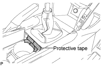
| 8. REMOVE UPPER CONSOLE PANEL (for Manual Transaxle) |
Open the lid of the upper console panel.
Apply protective tape to the area shown in the illustration.
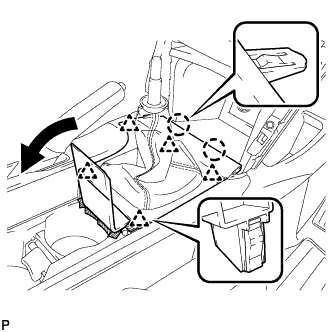
Using a moulding remover, disengage the 2 claws and the 5 clips, and then remove the upper console panel as shown in the illustration.
with Seat Heater System:
Disconnect each connector.
| 9. REMOVE UPPER CONSOLE REAR PANEL SUB-ASSEMBLY (for Automatic Transaxle) |
Disengage the 3 claws and the 5 clips.
Disconnect the connector and remove the upper console rear panel sub-assembly.
| 10. REMOVE UPPER CONSOLE REAR PANEL SUB-ASSEMBLY (for Manual Transaxle) |
Disengage the 3 claws and the 5 clips, and remove the upper console rear panel sub-assembly.
| 11. REMOVE UPPER CONSOLE PANEL SUB-ASSEMBLY |
Remove the 2 screws <F>.
Disengage the 4 claws.
Disconnect each connector and remove the upper console panel sub-assembly.
- HINT:
- Set the shift lever in the D position.
| 12. REMOVE FRONT DOOR SCUFF PLATE LH |
Disengage the 7 claws and 3 clips, and remove the front door scuff plate LH.
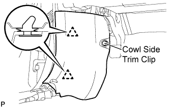
| 13. REMOVE COWL SIDE TRIM SUB-ASSEMBLY LH |
Remove the cowl side trim clip.
Disengage the 2 clips and remove the cowl side trim sub-assembly LH.
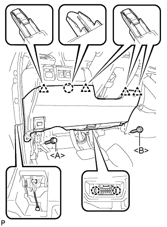
| 14. REMOVE LOWER INSTRUMENT PANEL FINISH PANEL LH |
Remove the bolt <A> and the screw <B>.
Disengage the 2 claws and the DLC3.
Disconnect the hood lock control cable assembly.
Disengage the claw and the 4 clips.
Remove the air hose, disconnect the connector, and then remove the lower instrument panel finish panel LH.
| 15. REMOVE FRONT DOOR SCUFF PLATE RH |
- HINT:
- Use the same procedures for the RH side and the LH side.
| 16. REMOVE COWL SIDE TRIM SUB-ASSEMBLY RH |
- HINT:
- Use the same procedures for the RH side and the LH side.
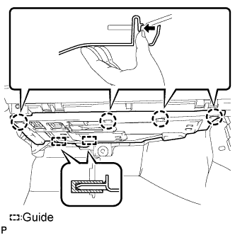
| 17. REMOVE INSTRUMENT PANEL NO. 2 UNDER COVER SUB-ASSEMBLY |
Disengage the 4 claws.
Disengage the 2 guides and remove the No. 2 under cover sub-assembly.
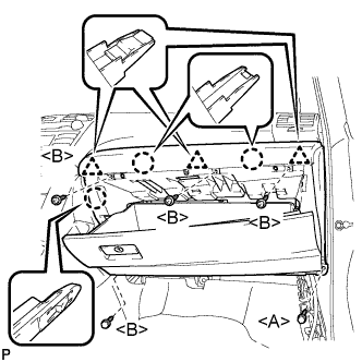
| 18. REMOVE LOWER INSTRUMENT PANEL SUB-ASSEMBLY |
Remove the bolt <A>.
Remove the 4 screws <B>.
Disengage the 3 claws and 3 clips, and then remove the lower instrument panel sub-assembly.
| 19. REMOVE CONSOLE BOX POCKET |
Remove the console box pocket.
| 20. REMOVE CONSOLE BOX CARPET |
Remove the console box carpet.
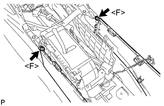
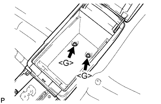
| 21. REMOVE CONSOLE BOX ASSEMBLY |
Remove the 2 screws <F>.
Remove the 2 bolts <G> and the console box assembly.
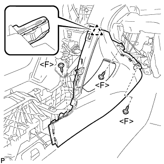
| 22. REMOVE NO. 1 CONSOLE BOX INSERT FRONT |
Remove the 3 screws <F>.
Disengage the clip and remove the No. 1 console box insert front.
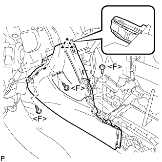
| 23. REMOVE NO. 2 CONSOLE BOX INSERT FRONT |
Remove the 3 screws <F>.
Disengage the clip and remove the No. 2 console box insert front.
| 24. REMOVE NO. 1 CONSOLE BOX DUCT (w/ Rear Register Duct) |
Remove the clip and No. 1 console box duct.
| 25. REMOVE CENTER AIRBAG SENSOR ASSEMBLY |
Turn back the carpet.
Disconnect the holder (with connectors).
Remove the 3 bolts and center airbag sensor assembly.