Air Conditioning System Plasmacluster Circuit
DESCRIPTION
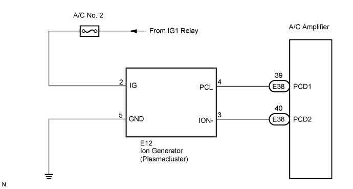
WIRING DIAGRAM
INSPECTION PROCEDURE
INSPECT AIR CONDITIONING AMPLIFIER
CHECK HARNESS AND CONNECTOR (ION GENERATOR - BODY GROUND)
CHECK HARNESS AND CONNECTOR (ION GENERATOR - BATTERY)
CHECK HARNESS AND CONNECTOR (ION GENERATOR - A/C AMPLIFIER)
AIR CONDITIONING SYSTEM - Plasmacluster Circuit |
DESCRIPTION
The plasmacluster operates in conjunction with blower switch operation. The plasmacluster operation indicator (CLEAN, ION) illuminates on the A/C control assembly when the plasmacluster is operating. When the plasmacluster is operating, the operation mode automatically switches between the sterilization mode (CLEAN) and the negative ion mode (ION) every 15 minutes.
WIRING DIAGRAM
INSPECTION PROCEDURE
| 1.INSPECT AIR CONDITIONING AMPLIFIER |
Remove the A/C amplifier with the connectors still connected.
Turn the ignition switch to the ON position.
Measure the voltage according to the value(s) in the table below.
- Standard voltage:
- CLEAN mode:
Tester Connection (Symbols)
| Condition
| Specified Condition
|
E38-39 (PCD1) - Body ground
| Ignition switch: ON
Blower switch: OFF
| 10 to 14 V
|
E38-39 (PCD1) - Body ground
| Ignition switch: ON
Blower switch: ON
| Below 1 V
|
- ION Mode:
Tester Connection (Symbols)
| Condition
| Specified Condition
|
E38-40 (PCD2) - Body ground
| Ignition switch: ON
Blower switch: OFF
| 10 to 14 V
|
E38-40 (PCD2) - Body ground
| Ignition switch: ON
Blower switch: ON
| Below 1 V
|
| OK |
|
|
|
| PROCEED TO NEXT CIRCUIT INSPECTION SHOWN IN PROBLEM SYMPTOMS TABLE |
|
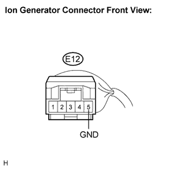
| 2.CHECK HARNESS AND CONNECTOR (ION GENERATOR - BODY GROUND) |
Disconnect the connector from the ion generator.
Measure the resistance according to the value(s) in the table below.
- Standard resistance:
Tester Connection
(Symbols)
| Condition
| Specified Condition
|
E12-5 (GND) - Body ground
| Always
| Below 1 Ω
|
| | REPAIR OR REPLACE HARNESS OR CONNECTOR |
|
|
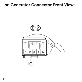
| 3.CHECK HARNESS AND CONNECTOR (ION GENERATOR - BATTERY) |
Measure the voltage according to the value(s) in the table below.
- Standard voltage:
Tester Connection
(Symbols)
| Condition
| Specified Condition
|
E12-2 (IG) - Body ground
| Ignition switch: LOCK
| Below 1 V
|
E12-2 (IG) - Body ground
| Ignition switch: ON
| 10 to 14 V
|
| | REPAIR OR REPLACE HARNESS OR CONNECTOR |
|
|
| 4.CHECK HARNESS AND CONNECTOR (ION GENERATOR - A/C AMPLIFIER) |
Disconnect the connector from the A/C amplifier.
Measure the resistance according to the value(s) in the table below.
- Standard resistance:
Tester Connection
(Symbols)
| Condition
| Specified Condition
|
E12-4 (PCL) - E38-39 (PCD1)
| Always
| Below 1 Ω
|
E12-4 (PCL) - Body ground
| Always
| 10 kΩ or higher
|
E12-3 (ION-) - E38-40 (PCD2)
| Always
| Below 1 Ω
|
E12-3 (ION-) - Body ground
| Always
| 10 kΩ or higher
|
| | REPAIR OR REPLACE HARNESS OR CONNECTOR |
|
|