Parking Brake Pedal Installation
Brake. Camry. Acv40 Gsv40
INSTALL PARKING BRAKE PEDAL ASSEMBLY (for LHD)
INSTALL PARKING BRAKE PEDAL ASSEMBLY (for RHD)
INSTALL NO. 1 AIR DUCT SUB-ASSEMBLY (for RHD)
CONNECT NO. 4 PARKING BRAKE CABLE ASSEMBLY
INSTALL CENTER AIRBAG SENSOR ASSEMBLY
INSTALL FLOOR SHIFT LEVER ASSEMBLY
INSTALL YAW RATE AND ACCELERATION SENSOR (w/ VSC)
INSTALL FLOOR CARPET BRACKET LH
INSTALL FLOOR CARPET BRACKET RH
INSTALL NO. 1 CONSOLE BOX DUCT (w/ Rear Register Duct)
INSTALL NO. 2 CONSOLE BOX INSERT FRONT
INSTALL NO. 1 CONSOLE BOX INSERT FRONT
INSTALL CONSOLE BOX ASSEMBLY
INSTALL CONSOLE BOX CARPET
INSTALL CONSOLE BOX POCKET
INSTALL UPPER CONSOLE PANEL SUB-ASSEMBLY
INSTALL UPPER CONSOLE REAR PANEL SUB-ASSEMBLY
INSTALL FLOOR SHIFT POSITION INDICATOR HOUSING SUB-ASSEMBLY
INSTALL NO. 1 INSTRUMENT CLUSTER FINISH PANEL GARNISH
INSTALL NO. 2 INSTRUMENT CLUSTER FINISH PANEL GARNISH
INSTALL SHIFT LEVER KNOB SUB-ASSEMBLY
INSTALL LOWER INSTRUMENT PANEL SUB-ASSEMBLY
INSTALL INSTRUMENT PANEL NO. 2 UNDER COVER SUB-ASSEMBLY
INSTALL COMBINATION METER ASSEMBLY (for RHD)
INSTALL INSTRUMENT CLUSTER FINISH PANEL NO.1 (for RHD)
INSTALL LOWER INSTRUMENT PANEL FINISH PANEL (for RHD)
INSTALL NO. 1 INSTRUMENT PANEL SUB-ASSEMBLY (for RHD)
INSTALL LOWER INSTRUMENT PANEL FINISH PANEL LH
INSTALL COWL SIDE TRIM SUB-ASSEMBLY LH
INSTALL FRONT DOOR SCUFF PLATE LH
INSTALL COWL SIDE TRIM SUB-ASSEMBLY RH
INSTALL FRONT DOOR SCUFF PLATE RH
CONNECT CABLE TO NEGATIVE BATTERY TERMINAL
INSPECT SENSOR SIGNAL
Parking Brake Pedal -- Installation |
| 1. INSTALL PARKING BRAKE PEDAL ASSEMBLY (for LHD) |
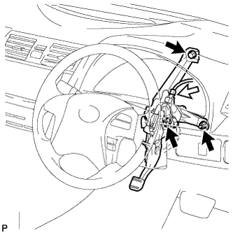
Install the parking brake pedal assembly with the bolt and 2 nuts.
- Torque:
- 39 N*m{398 kgf*cm, 29 ft.*lbf}
Connect the parking brake switch connector.
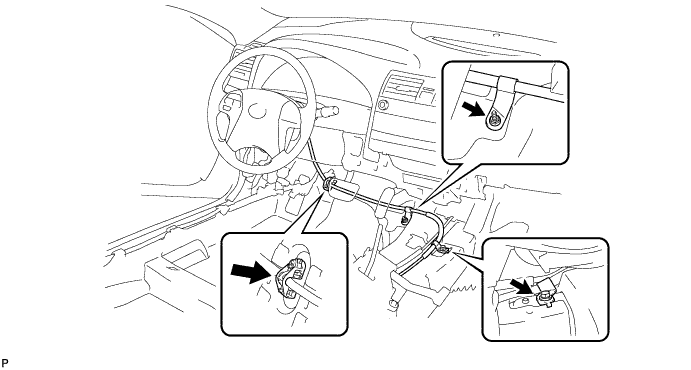
Install the No. 1 parking brake cable assembly to the body with the bolt, the nut, and a new No. 1 parking brake cable clamp.
- Torque:
- Bolt:
- 15 N*m{153 kgf*cm, 11 ft.*lbf}
- Nut:
- 5.4 N*m{55 kgf*cm, 48 in.*lbf}
Using a brass bar and a hammer, install the clip to the No. 1 parking brake cable assembly.
| 2. INSTALL PARKING BRAKE PEDAL ASSEMBLY (for RHD) |
Install the parking brake pedal assembly with the bolt and 2 nuts.
- Torque:
- 15 N*m{153 kgf*cm, 11 ft.*lbf}
Connect the parking brake switch connector.
Install the No. 1 parking brake cable assembly to the body with the bolt.
- Torque:
- 15 N*m{153 kgf*cm, 11 ft.*lbf}
Using a brass bar and a hammer, install the clip to the No. 1 parking brake cable sub-assembly.
| 3. INSTALL NO. 1 AIR DUCT SUB-ASSEMBLY (for RHD) |
Engage the 3 claws and install the No. 1 air duct sub-assembly.
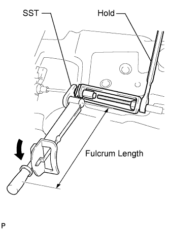
| 4. CONNECT NO. 4 PARKING BRAKE CABLE ASSEMBLY |
Connect the No. 4 parking brake cable assembly to the No. 1 parking brake cable assembly.
Using SST and a wrench, hold the lock nut of the No. 1 parking brake cable and tighten the turnbuckle of the No. 4 parking brake cable assembly.
- SST
- 09023-00101
- Torque:
- without SST:
- 5.4 N*m{55 kgf*cm, 48 in.*lbf}
- with SST:
- 5.0 N*m{51 kgf*cm, 44 in.*lbf}
- NOTICE:
- Use a torque wrench with a fulcrum length of 250 mm (9.84 in.).
- This torque is effective when SST is parallel to a torque wrench.
| 5. INSTALL CENTER AIRBAG SENSOR ASSEMBLY |
Check that the ignition switch is off.
Check that the battery negative (-) cable is disconnected.
- CAUTION:
- Wait for 90 seconds after disconnecting the cable to prevent airbag deployment.
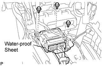
Install the center airbag sensor assembly with the 3 bolts.
- Torque:
- 17.5 N*m{179 kgf*cm, 13 ft.*lbf}
- NOTICE:
- If the center airbag sensor assembly has been dropped, or there are any cracks, dents or other defects in the case, bracket or connector, replace it with a new one.
- When installing the center airbag sensor assembly, be careful that the SRS wiring does not interfere with other parts and that it is not pinched between other parts.
Check that there is no looseness in the installation parts of the center airbag sensor assembly.
Connect the holder (with connectors).
Check that the water-proof sheet is properly set.
| 6. INSTALL FLOOR SHIFT LEVER ASSEMBLY |
Install the floor shift lever assembly with the 4 bolts.
- Torque:
- 12 N*m{122 kgf*cm, 8.9 ft.*lbf}
| 7. INSTALL YAW RATE AND ACCELERATION SENSOR (w/ VSC) |
Install the yaw rate and acceleration sensor with the 2 bolts.
- NOTICE:
- Do not damage the yaw rate and acceleration sensor.
- Make sure that the yaw rate and acceleration sensor is installed securely.
- Torque:
- 13 N*m{133 kgf*cm, 10 ft.*lbf}
Connect the yaw rate and acceleration sensor connector.
| 8. INSTALL FLOOR CARPET BRACKET LH |
| 9. INSTALL FLOOR CARPET BRACKET RH |
| 10. INSTALL NO. 1 CONSOLE BOX DUCT (w/ Rear Register Duct) |
Install the No. 1 console box duct with the clip.
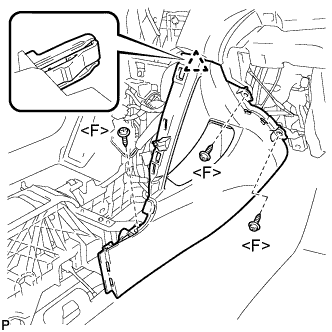
| 11. INSTALL NO. 2 CONSOLE BOX INSERT FRONT |
Engage the clip.
Install the No. 2 console box insert front with the 3 screws <F>.
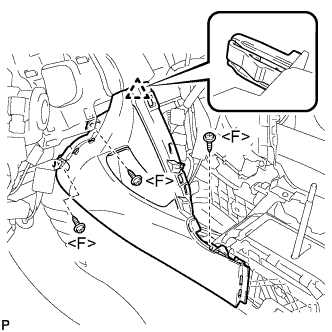
| 12. INSTALL NO. 1 CONSOLE BOX INSERT FRONT |
Engage the clip.
Install the No. 1 console box insert front with the 3 screws <F>.
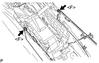
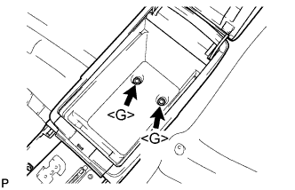
| 13. INSTALL CONSOLE BOX ASSEMBLY |
Install the 2 screws <F>.
Install the console box assembly with the 2 bolts <G>.
| 14. INSTALL CONSOLE BOX CARPET |
Install the console box carpet.
| 15. INSTALL CONSOLE BOX POCKET |
Install the console box pocket.
| 16. INSTALL UPPER CONSOLE PANEL SUB-ASSEMBLY |
Connect each connector.
Engage the 4 claws.
Install the upper console panel sub-assembly with the 2 screws <F>.
| 17. INSTALL UPPER CONSOLE REAR PANEL SUB-ASSEMBLY |
Connect the connector.
Engage the 3 claws and 5 clips to install the upper console rear panel sub-assembly.
| 18. INSTALL FLOOR SHIFT POSITION INDICATOR HOUSING SUB-ASSEMBLY |
with Seat Heater System:
Connect each connector.
Engage the 6 claws and the 3 clips to install the floor shift position indicator housing sub-assembly.
| 19. INSTALL NO. 1 INSTRUMENT CLUSTER FINISH PANEL GARNISH |
Engage the 2 clips and install the No. 1 instrument cluster finish panel garnish.
| 20. INSTALL NO. 2 INSTRUMENT CLUSTER FINISH PANEL GARNISH |
Engage the 2 clips and install the No. 2 instrument cluster finish panel garnish.
| 21. INSTALL SHIFT LEVER KNOB SUB-ASSEMBLY |
Install the shift lever knob sub-assembly.
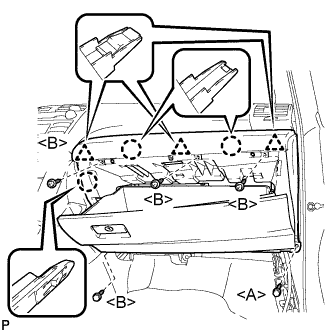
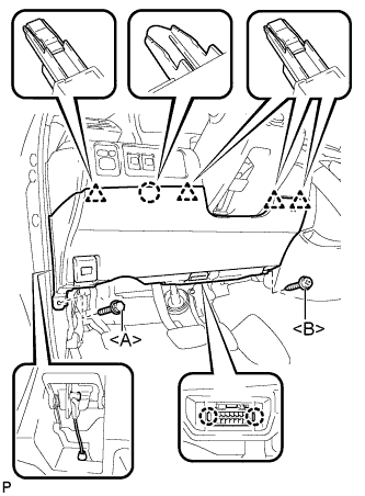
| 22. INSTALL LOWER INSTRUMENT PANEL SUB-ASSEMBLY |
Engage the 3 claws and 3 clips.
Install the 4 screws <B>.
Install the lower instrument panel sub-assembly with the bolt <A>.
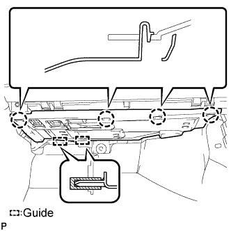
| 23. INSTALL INSTRUMENT PANEL NO. 2 UNDER COVER SUB-ASSEMBLY |
Engage the 4 claws and 2 guides and install the instrument panel No. 2 under cover.
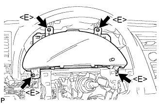
| 24. INSTALL COMBINATION METER ASSEMBLY (for RHD) |
Connect each connector.
Install the combination meter assembly with the 4 screws <E>.
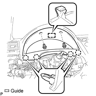
| 25. INSTALL INSTRUMENT CLUSTER FINISH PANEL NO.1 (for RHD) |
Engage the guide and the 4 claws.
Install the instrument cluster finish panel with the 2 clips.
| 26. INSTALL LOWER INSTRUMENT PANEL FINISH PANEL (for RHD) |
- HINT:
- w/o Entry and Start System: CAMRY_ACV40 RM0000024DA049X_01_0041.html
- w/ Entry and Start System: CAMRY_ACV40 RM0000024DA049X_01_0080.html
| 27. INSTALL NO. 1 INSTRUMENT PANEL SUB-ASSEMBLY (for RHD) |
Connect each connector.
Engage the 3 claws and 2 clips to install the No. 1 instrument panel sub-assembly.
| 28. INSTALL LOWER INSTRUMENT PANEL FINISH PANEL LH |
Install the air hose and connect the connector.
Engage the 2 claws and the DLC3.
Engage the claw and the 4 clips.
Instal the lower instrument panel finish panel LH with the screw <B> and bolt <A>.
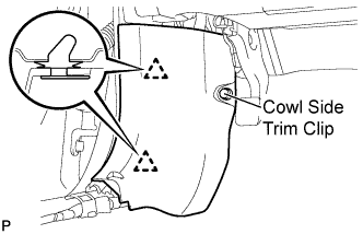
| 29. INSTALL COWL SIDE TRIM SUB-ASSEMBLY LH |
Engage the 2 clips.
Install the cowl side trim sub-assembly LH with the cowl side trim clip.
| 30. INSTALL FRONT DOOR SCUFF PLATE LH |
Engage the 7 claws and 3 clips, then install the front door scuff plate LH.
| 31. INSTALL COWL SIDE TRIM SUB-ASSEMBLY RH |
- HINT:
- Use the same procedures for the RH side and the LH side.
| 32. INSTALL FRONT DOOR SCUFF PLATE RH |
- HINT:
- Use the same procedures for the RH side and the LH side.
| 33. CONNECT CABLE TO NEGATIVE BATTERY TERMINAL |
| 34. INSPECT SENSOR SIGNAL |
- HINT:
- (CAMRY_ACV40 RM000000XHT03NX.html)