Dtc C1249/49 Open In Stop Light Switch Circuit
Brake. Camry. Acv40 Gsv40
DESCRIPTION
WIRING DIAGRAM
INSPECTION PROCEDURE
CHECK STOP LIGHT SWITCH OPERATION (STOP LIGHT SWITCH CIRCUIT)
INSPECT SKID CONTROL ECU CONNECTOR (STP TERMINAL)
INSPECT SKID CONTROL ECU CONNECTOR (GND TERMINAL CONTINUITY)
RECONFIRM DTC
INSPECT STOP LIGHT SWITCH ASSEMBLY (POWER SOURCE TERMINAL VOLTAGE)
INSPECT STOP LIGHT SWITCH ASSEMBLY
CHECK HARNESS AND CONNECTOR (STOP LIGHT SWITCH TO SKID CONTROL ECU)
DTC C1249/49 Open in Stop Light Switch Circuit |
DESCRIPTION
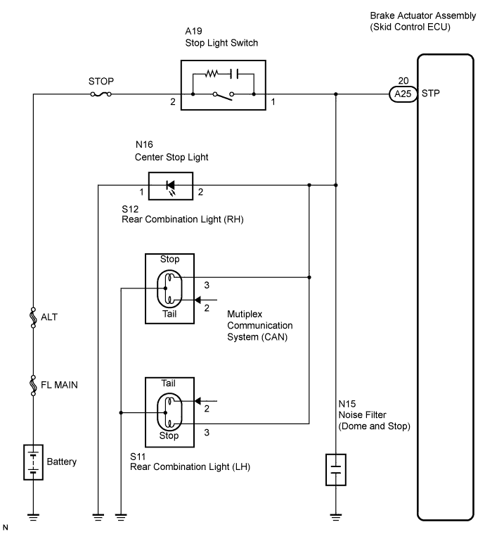
This circuit recognizes brake operation by sending a stop light signal to the skid control ECU.The skid control ECU has an open detection circuit, which outputs this DTC when detecting an open in the stop light signal input line (STP terminal) or the ground line of the stop light circuit with the stop light switch off (brake pedal not depressed).DTC No.
| DTC Detecting Condition
| Trouble Area
|
C1249/49
| Stop light switch circuit is open, and stop light switch voltage is 40% or more and less than 67% of the battery voltage.
| - Stop light switch
- Stop light switch circuit
- Brake actuator assembly (Skid Control ECU)
|
WIRING DIAGRAM
INSPECTION PROCEDURE
- HINT:
- Check the condition of each related circuit connector before troubleshooting (CAMRY_ACV40 RM000000UZ301ZX.html).
| 1.CHECK STOP LIGHT SWITCH OPERATION (STOP LIGHT SWITCH CIRCUIT) |
Check that the stop lights come on when the brake pedal is depressed and goes off when the brake pedal is released.
- OK:
Pedal Condition
| Illumination Condition
|
Brake pedal depressed
| ON
|
Brake pedal released
| OFF
|
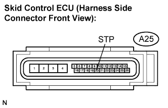
| 2.INSPECT SKID CONTROL ECU CONNECTOR (STP TERMINAL) |
Disconnect the skid control ECU connector.
Measure the voltage according to the value(s) in the table below.
- Standard voltage:
Tester Connection
| Switch Condition
| Specified Condition
|
A25-20 (STP) - Body ground
| Brake pedal depressed
| 8 to 14 V
|
A25-20 (STP) - Body ground
| Brake pedal released
| Below 4.0 V
|
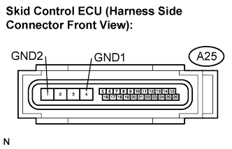
| 3.INSPECT SKID CONTROL ECU CONNECTOR (GND TERMINAL CONTINUITY) |
Measure the resistance according to the value(s) in the table below.
- Standard resistance:
Tester Connection
| Specified Condition
|
A25-4 (GND1) - Body ground
| Below 1 Ω
|
A25-1 (GND2) - Body ground
| Below 1 Ω
|
Connect the connector.
| | REPAIR OR REPLACE HARNESS OR CONNECTOR (GND CIRCUIT) |
|
|
Clear the DTC (CAMRY_ACV40 RM000001JB8003X.html).
Start the engine.
Depress the brake pedal several times to test the stop light circuit.
Check if the same DTC is recorded (CAMRY_ACV40 RM000001JB8003X.html).
- HINT:
- Reinstall the sensors, connectors, etc. and restore the vehicle to its prior condition before rechecking for DTCs.
- Result:
Condition
| Proceed to
|
DTC is not output
| A
|
DTC is output (When troubleshooting in accordance with the DTC CHART)
| B
|
DTC is output (When troubleshooting in accordance with the PROBLEM SYMPTOMS TABLE)
| C
|
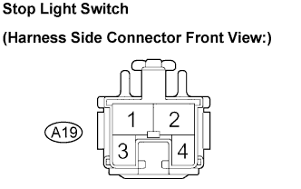
| 5.INSPECT STOP LIGHT SWITCH ASSEMBLY (POWER SOURCE TERMINAL VOLTAGE) |
Disconnect the stop light switch connector.
Measure the voltage according to the value(s) in the table below.
- Standard voltage:
Tester Connection
| Condition
| Specified Condition
|
A19-2 - Body ground
| Always
| 10 to 14 V
|
| | REPAIR OR REPLACE HARNESS OR CONNECTOR (POWER SOURCE CIRCUIT) |
|
|
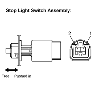
| 6.INSPECT STOP LIGHT SWITCH ASSEMBLY |
Measure the resistance according to the value(s) in the table below.
- Standard resistance:
Tester Connection
| Condition
| Specified Condition
|
Switch pin free
| 1 - 2
| Below 1 Ω
|
Switch pin pushed in
| 1 - 2
| 10 kΩ or higher
|
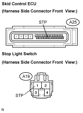
| 7.CHECK HARNESS AND CONNECTOR (STOP LIGHT SWITCH TO SKID CONTROL ECU) |
Disconnect the stop light switch connector and skid control ECU connector.
Measure the resistance according to the value(s) in the table below.
- Standard resistance:
Tester Connection
| Specified Condition
|
A25-20 (STP) - A19-1 (STP)
| Below 1 Ω
|
Connect the connector.
| | REPAIR OR REPLACE HARNESS OR CONNECTOR (STOP LIGHT SWITCH TO SKID CONTROL ECU) |
|
|
| OK |
|
|
|
| REPAIR OR REPLACE HARNESS OR CONNECTOR (STOP LIGHT CIRCUIT) |
|