Clutch Master Cylinder Installation
INSTALL CLUTCH MASTER CYLINDER ASSEMBLY (for LHD)
INSTALL CLUTCH MASTER CYLINDER ASSEMBLY (for RHD)
CONNECT CLUTCH LINE
CONNECT CLUTCH RESERVOIR TUBE
CONNECT CLUTCH MASTER CYLINDER PUSH ROD CLEVIS
INSTALL BRAKE BOOSTER ASSEMBLY (for LHD)
INSTALL COMBINATION METER ASSEMBLY
INSTALL INSTRUMENT CLUSTER FINISH PANEL NO.1
INSTALL LOWER INSTRUMENT PANEL FINISH PANEL
INSTALL NO. 1 INSTRUMENT PANEL SUB-ASSEMBLY
INSTALL LOWER INSTRUMENT PANEL FINISH PANEL LH
INSTALL COWL SIDE TRIM SUB-ASSEMBLY LH
INSTALL FRONT DOOR SCUFF PLATE LH
INSTALL COWL TOP PANEL OUTER SUB-ASSEMBLY
INSTALL WIND SHIELD WIPER LINK ASSEMBLY
INSTALL AIR CLEANER CASE SUB-ASSEMBLY (for LHD)
INSTALL AIR CLEANER CAP SUB-ASSEMBLY (for LHD)
CONNECT CABLE TO NEGATIVE BATTERY TERMINAL
BLEED CLUTCH PIPE LINE
CHECK BRAKE FLUID
CHECK FLUID LEVEL IN RESERVOIR
INSPECT AND ADJUST CLUTCH PEDAL SUB-ASSEMBLY
Clutch Master Cylinder -- Installation |
| 1. INSTALL CLUTCH MASTER CYLINDER ASSEMBLY (for LHD) |
Install a new gasket to the clutch master cylinder assembly.
Install the clutch master cylinder with the 2 nuts.
- Torque:
- 12 N*m{120 kgf*cm, 9 ft.*lbf}
| 2. INSTALL CLUTCH MASTER CYLINDER ASSEMBLY (for RHD) |
Install a new gasket to the clutch master cylinder assembly.
Install the clutch master cylinder with the 2 nuts.
- Torque:
- 12 N*m{120 kgf*cm, 9 ft.*lbf}
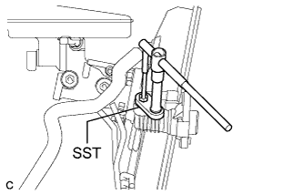
Using SST, connect the clutch line.
- SST
- 09023-00101
- Torque:
- 15 N*m{155 kgf*cm, 11 ft.*lbf}
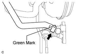
| 4. CONNECT CLUTCH RESERVOIR TUBE |
Connect the clutch reservoir tube to the clutch master cylinder with the clip.
- NOTICE:
- Connect the clutch reservoir tube so that it will not be twisted.
- Make sure that the green mark is positioned as shown in the illustration.
| 5. CONNECT CLUTCH MASTER CYLINDER PUSH ROD CLEVIS |
Apply MP grease to the contact surface of the pin and clevis bushing.
Connect the clevis to the clutch pedal with the pin and a new clip.
- HINT:
- Install the pin from the left side of the vehicle.
| 6. INSTALL BRAKE BOOSTER ASSEMBLY (for LHD) |
CAMRY_ACV40 RM0000022JH00SX.html.
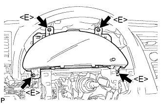
| 7. INSTALL COMBINATION METER ASSEMBLY |
Connect each connector.
Install the combination meter assembly with the 4 screws <E>.
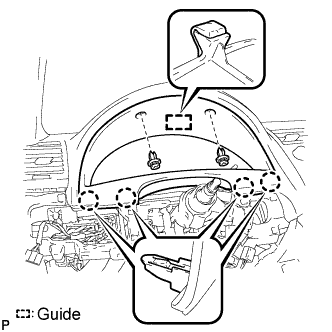
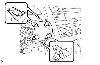
| 8. INSTALL INSTRUMENT CLUSTER FINISH PANEL NO.1 |
Engage the guide and the 4 claws.
Install the instrument cluster finish panel with the 2 clips.
| 9. INSTALL LOWER INSTRUMENT PANEL FINISH PANEL |
Engage the 2 claws and 2 clips to install the lower instrument panel finish panel.
| 10. INSTALL NO. 1 INSTRUMENT PANEL SUB-ASSEMBLY |
Connect each connector.
Engage the 3 claws and 2 clips to install the No. 1 instrument panel sub-assembly.
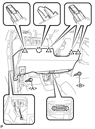
| 11. INSTALL LOWER INSTRUMENT PANEL FINISH PANEL LH |
Install the air hose and connect the connector.
Engage the 2 claws and the DLC3.
Engage the claw and the 4 clips.
Instal the lower instrument panel finish panel LH with the screw <B> and bolt <A>.
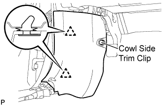
| 12. INSTALL COWL SIDE TRIM SUB-ASSEMBLY LH |
Engage the 2 clips.
Install the cowl side trim sub-assembly LH with the cowl side trim clip.
| 13. INSTALL FRONT DOOR SCUFF PLATE LH |
Engage the 7 claws and 3 clips, then install the front door scuff plate LH.
| 14. INSTALL COWL TOP PANEL OUTER SUB-ASSEMBLY |
Install the outer cowl top panel sub-assembly with the 4 bolts and 4 nuts.
- Torque:
- :
- N*m{ kgf*cm}
- Bolt:
- 5.0 N*m{51 kgf*cm, 44 in.*lbf}
- Nut:
- 85 N*m{867 kgf*cm, 62 ft.*lbf}
| 15. INSTALL WIND SHIELD WIPER LINK ASSEMBLY |
CAMRY_ACV40 RM0000023QU002X.html.
| 16. INSTALL AIR CLEANER CASE SUB-ASSEMBLY (for LHD) |
Install the air cleaner case with the 3 bolts.
- Torque:
- 5.0 N*m{51 kgf*cm, 44 in.*lbf}
Connect the hose clamp.
| 17. INSTALL AIR CLEANER CAP SUB-ASSEMBLY (for LHD) |
Install the air cleaner filter element onto the air cleaner case.
Insert the hinges. Install the air cleaner cap sub-assembly with the 2 bolts.
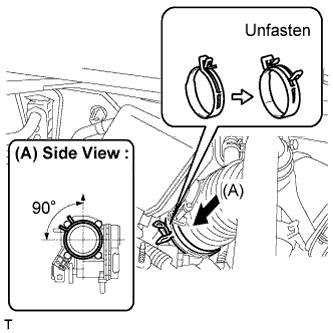
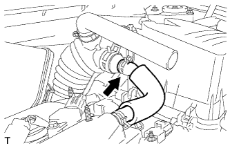
Align the matchmarks of the No. 1 air cleaner hose and throttle body, and then connect the air cleaner hose No. 1 to the throttle body and unfasten the No. 1 air cleaner hose clamp.
- NOTICE:
- Make sure that the hose clamp is at the correct angle.
Connect the No. 2 ventilation hose to the air cleaner hose.
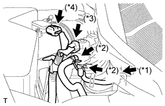
Connect the purge line hose to the clamp (*1).
Connect the 2 purge VSV vacuum hoses (*2).
Connect the purge VSV connector (*3).
Connect the mass air flow meter connector (*4).
| 18. CONNECT CABLE TO NEGATIVE BATTERY TERMINAL |
| 19. BLEED CLUTCH PIPE LINE |
Fill the brake reservoir with brake fluid and bleed the clutch system.
- Torque:
- 8.3 N*m{85 kgf*cm, 74 in.*lbf}
Check the brake fluid (CAMRY_ACV40 RM000000SRF007X.html).
- HINT:
- Check for leakage in the brake system.
- Check for leakage in the clutch system.
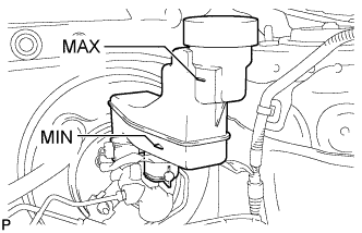
| 21. CHECK FLUID LEVEL IN RESERVOIR |
Check the fluid level.
If brake fluid level is lowered, check for leakage and inspect the disc brake pad. If necessary, refill the reservoir with brake fluid after repair and replacement.
- Fluid:
- SAE J1703 or FMVSS No. 116 DOT 3
| 22. INSPECT AND ADJUST CLUTCH PEDAL SUB-ASSEMBLY |
CAMRY_ACV40 RM0000015MO007X.html.