Brake Booster -- Installation |
| 1. INSTALL BRAKE MASTER CYLINDER PUSH ROD CLEVIS |
Temporarily install the lock nut and the brake master cylinder push rod clevis to the brake booster assembly.
- NOTICE:
- Fully tighten the lock nut after adjusting the pedal height.
- Torque:
- 26 N*m{265 kgf*cm, 19 ft.*lbf}
| 2. INSTALL BRAKE BOOSTER GASKET |
Install a new brake booster gasket.
 |
| 3. INSTALL BRAKE BOOSTER ASSEMBLY |
Install the brake booster assembly and the gasket with the 4 nuts.
- Torque:
- 13 N*m{133 kgf*cm, 10 ft.*lbf}
- NOTICE:
- Do not damage the brake lines.
 |
| 4. CONNECT NO. 2 VACUUM HOSE (for 2AZ-FE RHD) |
Connect the No. 2 vacuum hose and move the clip.
 |
| 5. INSTALL BRAKE MASTER CYLINDER SUB-ASSEMBLY |
- HINT:
- Refer to the procedures up to "INSTALLATION MASTER CYLINDER". (Link)
| 6. CONNECT NO. 2 VACUUM HOSE (for LHD) |
Connect the No. 2 vacuum hose and move the clip.
 |
| 7. CONNECT BRAKE MASTER CYLINDER PUSH ROD CLEVIS |
Apply the lithium soap base glycol grease to the push rod pin.
 |
Connect the brake master cylinder push rod clevis to the brake pedal with the push rod pin and a new clip as shown in the illustration.
| 8. INSTALL BRAKE PEDAL RETURN SPRING (for LHD) |
Install the brake pedal return spring.
 |
| 9. INSTALL BRAKE PEDAL RETURN SPRING (for RHD) |
Install the brake pedal return spring.
 |
| 10. CONNECT BRAKE LINE (for RHD) |
Install the brake lines to the clamp.
 |
Connect the 6 brake lines.
Without VSC (CAMRY_ACV40 RM0000013P401RX_01_0001.html)
With VSC (CAMRY_ACV40 RM0000013P401QX_01_0001.html)
| 11. CONNECT AIR CONDITIONING TUBE AND ACCESSORY (for RHD) |
Remove the attached vinyl tape from the tube.
Sufficiently apply compressor oil to a new O-ring and fitting surface of the air conditioning tube assembly.
- Compressor oil:
- ND-OIL 8 or equivalent
Install the O-ring on the air conditioning tube and accessory.
Install the air conditioner tube and accessory.
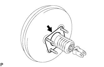
| 12. CONNECT SUCTION PIPE SUB-ASSEMBLY (for RHD) |
Remove the attached vinyl tape from the hose.
Sufficiently apply compressor oil to a new O-ring and the fitting surface of the suction hose sub-assembly.
- Compressor oil:
- ND-OIL 8 or equivalent
Install the O-ring on the suction hose sub-assembly.
Move the hook connector in the direction indicated by the arrow in the illustration.
 |
Insert the pipe joint into the fitting hole securely and tighten the bolt.
- Torque:
- 9.8 N*m{100 kgf*cm, 87 in.*lbf}
| 13. INSTALL ENGINE AND TRANSAXLE (for 2GR-FE RHD) |
- HINT:
- Refer to the procedures from "INSTALL MECHANICAL ENGINE ASSEMBLY (for 2GR-FE ENGINE)". (CAMRY_ACV40 RM0000021ZR022X.html)
| 14. CHARGE WITH REFRIGERANT (for RHD) |
Perform vacuum purging using a vacuum pump.
Charge with refrigerant HFC-134a (R134a).

- Standard:
- 450 to 550 g (15.9 to 19.4 oz.)
- SST
- 07110-58060(07117-58060,07117-58070,07117-58080,07117-58090,07117-78050,07117-88060,07117-88070,07117-88080)
- NOTICE:
- Do not turn the A/C on before charging with refrigerant. Doing so will cause the cooler compressor to work without refrigerant, resulting in overheating of the cooler compressor.
- Approximately 100 g (3.53 oz.) of refrigerant may need to be charged after bubbles disappear.
The refrigerant amount should be checked by quantity, not with the sight glass.
- HINT:
- Ensure that sufficient refrigerant is available to recharge the system when using a refrigerant recovery unit. Refrigerant recovery units are not always able to recover 100 % of the refrigerant from an A/C system.
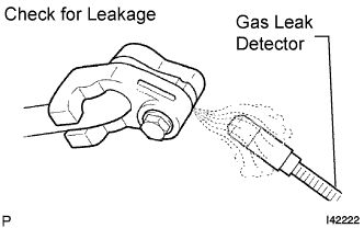
| 15. CHECK FOR LEAKAGE OF REFRIGERANT (for RHD) |
After recharging with refrigerant gas, check for leakage of refrigerant gas using a halogen leak detector.
Carry out the test under the following conditions:
- IG OFF
- Secure good ventilation (the gas leak detector may react to volatile gases which are not refrigerant, such as evaporated gasoline and exhaust gas).
- Repeat the test 2 or 3 times.
- Make sure that there is some refrigerant remaining in the refrigeration system.
When the compressor is off: approx. 392 to 588 kPa (4 to 6 kgf/cm2, 57 to 85 psi)
- IG OFF
Using a gas leak detector, check for leakage from the refrigerant lines.
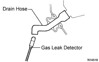
 |
Bring the gas leak detector close to the drain hose with the detector's power off, and then turn the detector on.
- HINT:
- After the blower motor has stopped, let the cooling unit stand for more than 15 minutes.
- Bring the gas leak detector sensor under the drain hose.
- When bringing the gas leak detector close to the drain hose, make sure that the gas leak detector does not react to volatile gases.
If it is not possible to avoid interference from volatile gases, the vehicle should be lifted up to allow testing.
 |
If a gas leak is not detected from the drain hose, remove the blower motor control from the cooling unit. Insert the gas leak detector sensor into the unit and perform the test.
Disconnect the pressure switch connector and leave it for approximately 20 minutes. Bring the gas leak detector close to the pressure switch and perform the test.