Can Communication System Main Body Ecu Communication Stop Mode
DESCRIPTION
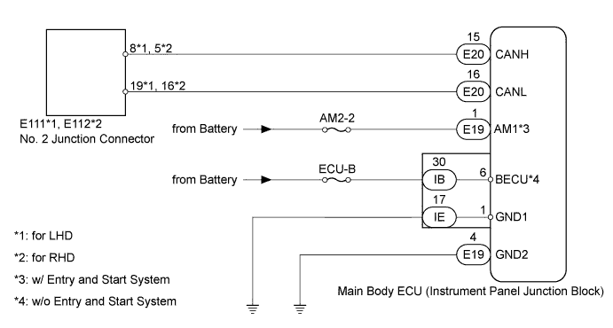
WIRING DIAGRAM
INSPECTION PROCEDURE
DISCONNECT CABLE FROM NEGATIVE BATTERY TERMINAL
CHECK CAN BUS LINE FOR DISCONNECTION (MAIN BODY ECU BRANCH WIRE)
CHECK HARNESS AND CONNECTOR (MAIN BODY ECU - BATTERY AND BODY GROUND)
CAN COMMUNICATION SYSTEM - Main Body ECU Communication Stop Mode |
DESCRIPTION
Detection Item
| Symptom
| Trouble Area
|
Main Body ECU Communication Stop Mode
| Either condition is met:
- "Main Body" is not displayed on "Bus Check".
- "Main Body ECU Communication Stop Mode" in "DTC Combination Table" applies.
| - Power source or inside main body ECU
- Main body ECU branch wire or connector
- Main body ECU
|
WIRING DIAGRAM
INSPECTION PROCEDURE
- NOTICE:
- Turn the ignition switch off before measuring the resistances of the main wire and the branch wire.
- For Auto:
After the ignition switch is turned off, check that the key reminder warning system is not in operation.
- For Reminder:
After the ignition switch is turned off, check that the key reminder warning system and light reminder buzzer are not in operation.
- Before measuring the resistance, leave the vehicle for at least 1 minute and do not operate the ignition switch, any switches or doors. If doors need to be opened in order to check connectors, open the doors and leave them open.
- HINT:
- Operating the ignition switch, any switches or any doors triggers related ECU and sensor communication with the CAN, which causes resistance variation.
| 1.DISCONNECT CABLE FROM NEGATIVE BATTERY TERMINAL |
Disconnect the cable from the negative (-) battery terminal before measuring the resistance of the main wire and the branch wire.
- CAUTION:
- Wait at least 90 seconds after disconnecting the cable from the negative (-) battery terminal to disable the SRS system.
- NOTICE:
- w/ Navigation System (for HDD):
After the ignition switch is turned off, the HDD navigation system requires approximately a minute to record various types of memory and settings. As a result, after turning the ignition switch off, wait a minute or more before disconnecting the cable from the negative (-) battery terminal.
- When disconnecting the cable, some systems need to be initialized after the cable is reconnected.
| 2.CHECK CAN BUS LINE FOR DISCONNECTION (MAIN BODY ECU BRANCH WIRE) |
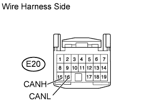
Disconnect the E20 main body ECU connector.
Measure the resistance according to the value(s) in the table below.
- Standard Resistance:
Tester Connection
| Switch Condition
| Specified Condition
|
E20-15 (CANH) - E20-16 (CANL)
| Ignition switch off
| 54 to 69 Ω
|
| | REPAIR OR REPLACE MAIN BODY ECU BRANCH WIRE OR CONNECTOR (CANH, CANL) |
|
|
| 3.CHECK HARNESS AND CONNECTOR (MAIN BODY ECU - BATTERY AND BODY GROUND) |
Connect the cable to the negative (-) battery terminal.
- NOTICE:
- When disconnecting the cable, some systems need to be initialized after the cable is reconnected.
Disconnect the E19, IB and IE main body ECU connectors.
Measure the resistance according to the value(s) in the table below.
- Standard Resistance:
Tester Connection
| Condition
| Specified Condition
|
IE-17 (GND1) - Body ground
| Always
| Below 1 Ω
|
E19-4 (GND2) - Body ground
| Always
| Below 1 Ω
|
Measure the voltage according to the value(s) in the table below.
- Standard Voltage:
w/ Entry and Start SystemTester Connection
| Condition
| Specified Condition
|
E19-1 (AM1) - Body ground
| Always
| 11 to 14 V
|
w/o Entry and Start SystemTester Connection
| Condition
| Specified Condition
|
IB-30 (BECU) - Body ground
| Always
| 11 to 14 V
|
| | REPAIR OR REPLACE HARNESS OR CONNECTOR |
|
|