Audio And Visual System Illumination Circuit
DESCRIPTION
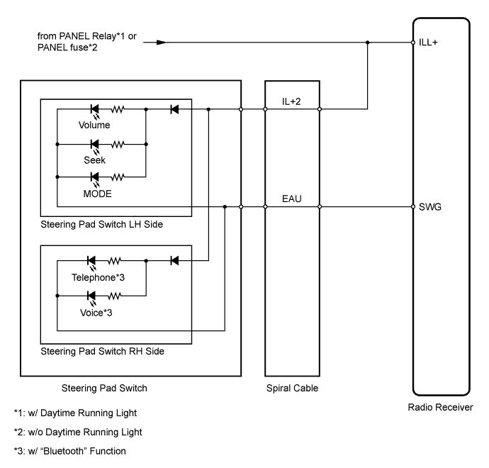
WIRING DIAGRAM
INSPECTION PROCEDURE
CHECK HARNESS AND CONNECTOR (RADIO RECEIVER - BATTERY AND BODY GROUND)
CHECK VEHICLE EQUIPMENT
CHECK HARNESS AND CONNECTOR (SPIRAL CABLE - RADIO RECEIVER)
INSPECT STEERING PAD SWITCH ASSEMBLY
INSPECT SPIRAL CABLE SUB-ASSEMBLY
AUDIO AND VISUAL SYSTEM - Illumination Circuit |
DESCRIPTION
The radio receiver panel illuminates when the light control switch is in the TAIL or HEAD position.
WIRING DIAGRAM
INSPECTION PROCEDURE
- NOTICE:
- The vehicle is equipped with an SRS such as the airbag. Before servicing (include removal or installation of parts), be sure to read the precautionary notice for the airbag system (RAV4_ACA30 RM000000XFC05IX.html).
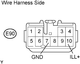
| 1.CHECK HARNESS AND CONNECTOR (RADIO RECEIVER - BATTERY AND BODY GROUND) |
Disconnect the E90 receiver connector.
Measure the voltage and resistance according to the value(s) in the table below.
- Standard Resistance:
Tester Connection
| Specified Condition
|
E90-7 (GND) - Body ground
| Below 1 Ω
|
- Standard Voltage:
Tester Connection
| Condition
| Specified Condition
|
E90-10 (ILL+) - Body ground
| Light control switch off
| Below 1 V
|
E90-10 (ILL+) - Body ground
| Light control switch TAIL or HEAD
| 11 to 14 V
|
| | REPAIR OR REPLACE HARNESS OR CONNECTOR |
|
|
| 2.CHECK VEHICLE EQUIPMENT |
Check if the steering pad switch is equipped on the vehicle.
ResultResult
| Proceed to
|
w/ Steering pad switch
| A
|
w/o Steering pad switch
| B
|
| | PROCEED TO NEXT INSPECTION PROCEDURE SHOWN IN PROBLEM SYMPTOMS TABLE |
|
|
| 3.CHECK HARNESS AND CONNECTOR (SPIRAL CABLE - RADIO RECEIVER) |
Disconnect the E10 spiral cable connector.
Disconnect the E92*1 or E107*2 radio receiver connector.
*1: except Europe
*2: for Europe
Measure the resistance and voltage according to the value(s) in the table below.
- Standard Resistance:
except EuropeTester Connection
| Specified Condition
|
E10-4 (EAU) - E92-6 (SWG)
| Below 1 Ω
|
for EuropeTester Connection
| Specified Condition
|
E10-4 (EAU) - E107-6 (SWG)
| Below 1 Ω
|
- Standard Voltage:
Tester Connection
| Condition
| Specified Condition
|
E10-12 (IL+2) - Body ground
| Light control switch
TAIL or HEAD
| 11 to 14 V
|
| | REPAIR OR REPLACE HARNESS OR CONNECTOR |
|
|
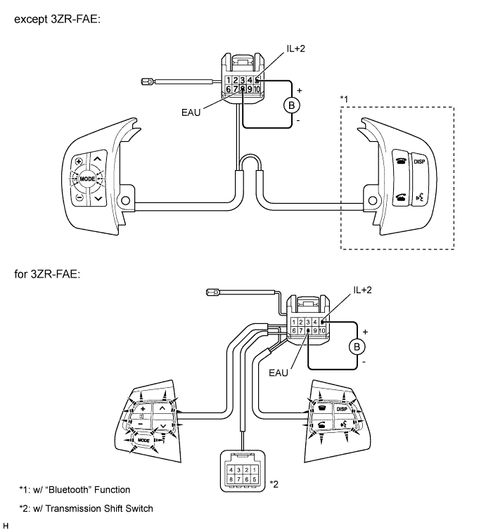
| 4.INSPECT STEERING PAD SWITCH ASSEMBLY |
Remove the steering pad switch (RAV4_ACA30 RM000001H7K00HX.html).
Connect the positive (+) lead of the battery to terminal 5 (IL+2) and the negative (-) lead to terminal 8 (EAU) of the switch connector.
Check if the illumination for the switch comes on.
- OK:
- Illumination for the steering pad switch comes on.
| | REPLACE STEERING PAD SWITCH ASSEMBLY |
|
|
| 5.INSPECT SPIRAL CABLE SUB-ASSEMBLY |
Remove the spiral cable (RAV4_ACA30 RM000001DNS00EX.html).
Measure the resistance according to the value(s) in the table below.
- Standard Resistance:
Tester Connection
| Condition
| Specified Condition
|
4 (EAU) - 8 (EAU)
| Spiral cable is turned 2.5 rotations counterclockwise
| Below 1 Ω
|
Spiral cable is centered
|
Spiral cable is turned 2.5 rotations clockwise
|
12 (IL+2) - 5 (IL+2)
| Spiral cable is turned 2.5 rotations counterclockwise
| Below 1 Ω
|
Spiral cable is centered
|
Spiral cable is turned 2.5 rotations clockwise
|
- NOTICE:
- The spiral cable is an important part of the SRS airbag system. Incorrect removal or installation of the spiral cable may prevent the airbag from deploying. Be sure to read the Precaution for the SRS (RAV4_ACA30 RM000000KT106QX.html).
| | REPLACE SPIRAL CABLE SUB-ASSEMBLY |
|
|
| OK |
|
|
|
| PROCEED TO NEXT INSPECTION PROCEDURE SHOWN IN PROBLEM SYMPTOMS TABLE |
|