Wireless Door Lock Control System (W/O Entry And Start System) No Answer-Back
Door Lock. Toyota Rav4. Aca30, 33, 38 Gsa33 Zsa30, 35
DESCRIPTION
WIRING DIAGRAM
INSPECTION PROCEDURE
READ VALUE USING INTELLIGENT TESTER (DOOR LOCK POSITION SWITCH)
CHECK WIRELESS DOOR LOCK CONTROL FUNCTION
PERFORM ACTIVE TEST USING INTELLIGENT TESTER (FLSH RELAY, TURN SIGNAL FLASHER RELAY)
CHECK HAZARD WARNING LIGHT
CHECK WIRE HARNESS (MAIN BODY ECU - TURN SIGNAL FLASHER RELAY)
WIRELESS DOOR LOCK CONTROL SYSTEM (w/o Entry and Start System) - No Answer-Back |
DESCRIPTION
In some cases, wireless door lock control functions are normal but the hazard warning lights answer-back function does not operate. In such cases, the main body ECU's hazard warning lights signal outputs may be malfunctioning.- NOTICE:
- Troubleshooting should be started after confirming that the customize status of the answer-back function.
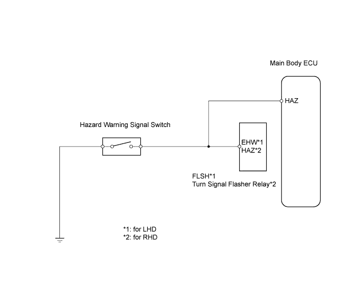
WIRING DIAGRAM
INSPECTION PROCEDURE
| 1.READ VALUE USING INTELLIGENT TESTER (DOOR LOCK POSITION SWITCH) |
Connect the intelligent tester to the DLC3.
Turn the ignition switch on (IG).
Turn the intelligent tester on.
Enter the following menus: Body / Main Body / Data List.
Read the Data List according to the display on the intelligent tester.
Main Body ECU:Item
| Measurement Item/Range (Display)
| Normal Condition
| Diagnostic Note
|
D-Door Lock Pos SW
| Driver side door lock position switch signal / ON or OFF
| ON: Driver side door is unlocked
OFF: Driver side door is locked
| -
|
P-Door Lock Pos SW
| Passenger side door lock position switch signal / ON or OFF
| ON: Passenger side door is unlocked
OFF: Passenger side door is locked
| -
|
- OK:
- The intelligent tester should display as shown in the table according to door lock operation.
| 2.CHECK WIRELESS DOOR LOCK CONTROL FUNCTION |
Check the wireless door lock control functions by operating the transmitter switches.
Result:Result
| Proceed to
|
Wireless door lock functions are normal but hazard warning light answer-back does not occur
| A
|
Wireless door lock functions are abnormal
| B
|
| | Go to PROBLEM SYMPTOMS TABLE |
|
|
| 3.PERFORM ACTIVE TEST USING INTELLIGENT TESTER (FLSH RELAY, TURN SIGNAL FLASHER RELAY) |
Select the Active Test, use the intelligent tester to generate a control command, and then check that the hazard warning lights flash.
Main body ECU:Item
| Test Details
| Diagnostic Note
|
Hazard
| Turns FLSH relay*1 (turn signal flasher relay*2) ON / OFF
| -
|
- HINT:
- *1: for LHD
- *2: for RHD
- OK:
- Hazard warning lights are turned ON / OFF
| | REPLACE INSTRUMENT PANEL JUNCTION BLOCK (MAIN BODY ECU) |
|
|
| 4.CHECK HAZARD WARNING LIGHT |
Check that the hazard warning lights flash continuously when the hazard warning signal switch is pressed.
Result:Result
| Proceed to
|
Hazard warning lights flash continuously (for RHD)
| A
|
Hazard warning lights do not flash continuously
| B
|
Hazard warning lights flash continuously (for LHD)
| C
|
| |
|
| | REPLACE INSTRUMENT PANEL JUNCTION BLOCK (MAIN BODY ECU) |
|
|
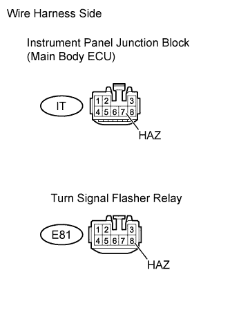
| 5.CHECK WIRE HARNESS (MAIN BODY ECU - TURN SIGNAL FLASHER RELAY) |
Disconnect the IT junction block connector.
Disconnect the E81 flasher connector.
Measure the resistance of the wire harness side connectors.
- Standard resistance:
Tester Connection
| Specified Condition
|
IT8-7 (HAZ) - E81-8 (HAZ)
| Below 1 Ω
|
IT8-7 (HAZ) or E81-8 (HAZ) - Body ground
| 10 kΩ or higher
|
| | REPAIR OR REPLACE HARNESS AND CONNECTOR |
|
|
| OK |
|
|
|
| REPLACE INSTRUMENT PANEL JUNCTION BLOCK (MAIN BODY ECU) |
|