Dtc C0273/13 Open In Abs Motor Relay Circuit
Brake. Toyota Rav4. Aca30, 33, 38 Gsa33 Zsa30, 35
DESCRIPTION
WIRING DIAGRAM
INSPECTION PROCEDURE
INSPECT FUSE (ABS1)
CHECK WIRE HARNESS (SKID CONTROL ECU - BATTERY AND BODY GROUND)
PERFORM ACTIVE TEST USING INTELLIGENT TESTER (MOTOR RELAY)
RECONFIRM DTC
DTC C0273/13 Open in ABS Motor Relay Circuit |
DTC C0274/14 Short to B+ in ABS Motor Relay Circuit |
DESCRIPTION
The ABS motor relay supplies the power to the ABS pump motor. While the ABS is activated, the ECU turns the motor relay ON and operates the ABS pump motor.DTC No.
| DTC Detection Condition
| Trouble Area
|
C0273/13
| When either condition below is met:
- All of following conditions continue for 0.2 seconds or more.
- IG1 terminal voltage between 9.5 V and 18.5 V.
- During initial check or ABS operation.
- Relay contact open when relay on.
- Both of following conditions continue for 0.12 seconds or more.
- IG1 terminal voltage is 9.5 V or less.
- Relay contact remains open when relay on.
| - ABS1 H-fuse
- Harness or connector (+BM circuit)
- Brake actuator (Skid control ECU)
|
C0274/14
| When motor relay off, motor relay remains closed for 4 seconds or more.
| - ABS1 H-fuse
- Harness or connector (+BM circuit)
- Brake actuator (Skid control ECU)
|
- HINT:
- C0273/13 and C0274/14: The skid control ECU begins to detect these DTCs when the vehicle speed exceeds 6 km/h (4 mph).
WIRING DIAGRAM
Refer to DTC C0226/21, C0236/22, C0246/23, C0256/24 (RAV4_ACA30 RM000000OS902HX_02.html).
INSPECTION PROCEDURE
Remove the ABS1 H-fuse from the engine room No. 1 relay block.
Measure the resistance of the fuse.
- Standard resistance:
- Below 1 Ω
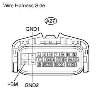
| 2.CHECK WIRE HARNESS (SKID CONTROL ECU - BATTERY AND BODY GROUND) |
Disconnect the A27 ECU connector.
Measure the voltage of the wire harness side connector.
- Standard voltage:
Tester Connection
| Specified Condition
|
A27-23 (+BM) - Body ground
| 11 to 14 V
|
Measure the resistance of the wire harness side connector.
- Standard resistance:
Tester Connection
| Specified Condition
|
A27-2 (GND1) - Body ground
| Below 1 Ω
|
A27-24 (GND2) - Body ground
| Below 1 Ω
|
| | REPAIR OR REPLACE HARNESS AND CONNECTOR |
|
|
| 3.PERFORM ACTIVE TEST USING INTELLIGENT TESTER (MOTOR RELAY) |
Select the Active Test, generate a control command, and then check that the motor relay operates.
Skid control ECUTester Display
| Test Parts
| Control Range
| Diagnostic Note
|
Motor Relay
| Turns ABS motor relay
| ON or OFF
| Operating sound of motor can be heard
|
- OK:
- Operation sound of the ABS motor is heard.
Clear the DTCs (RAV4_ACA30 RM000000ONJ02UX.html).
Start the engine.
Drive the vehicle at 6 km/h (4 mph) or more to activate the initial check.
Check if the same DTC(s) is output (RAV4_ACA30 RM000000ONJ02UX.html).
ResultResult
| Proceed to
|
DTC is output
| A
|
DTC is not output
| B
|