Front Shock Absorber With Coil Spring -- Installation |
- HINT:
- Use the same procedures for the RH side and LH side.
- The procedures listed below are for the LH side.
| 1. INSTALL FRONT SHOCK ABSORBER WITH COIL SPRING LH |
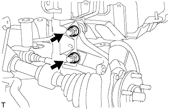
Install the front shock absorber with coil spring (upper side) with the 3 nuts.
- Torque:
- 50 N*m{510 kgf*cm, 37 ft.*lbf}
 |
Install the front shock absorber with coil spring to the steering knuckle with the 2 bolts and 2 nuts.
- Torque:
- 240 N*m{2447 kgf*cm, 177 ft.*lbf}
- NOTICE:
- Do not tighten the bolts.
 |
| 2. INSTALL FRONT STABILIZER LINK ASSEMBLY LH |
Install the link with the 2 nuts.
- Torque:
- 74 N*m{755 kgf*cm, 55 ft.*lbf}
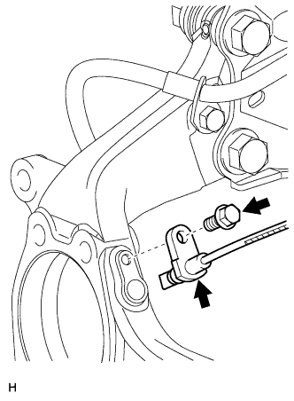
| 3. CONNECT FRONT SPEED SENSOR LH |
- NOTICE:
- To prevent interference with other parts, do not twist the painted line areas of the sensor wire when installing it.
Set the sensor into the knuckle, and then install the sensor with the bolt.
- Torque:
- 8.5 N*m{87 kgf*cm, 75 in.*lbf}
- NOTICE:
- Keep the sensor tip and sensor installation hole free from foreign matter.
- Firmly insert the sensor body into the knuckle before tightening the bolt.
- After installing the sensor to the knuckle, make sure that there is no clearance between the sensor stay and knuckle. Also make sure that no foreign matter is stuck between the parts.
- To prevent interference between the sensor and magnetic rotor, do not rotate the sensor body during or after the insertion of the sensor body to the knuckle.
 |
Install the sensor clamp and sensor clip as follows.

Simultaneously perform the following: 1) hang the hook part of the sensor clamp (labeled A) on the part of the flexible hose bracket (labeled C); and 2) insert the hook part of the sensor clamp (labeled B) to the part of the flexible hose bracket (labeled D).
- NOTICE:
- Do not twist the sensor wire when installing the clamp.
Install the sensor clamp to the flexible hose clamp and flexible hose bracket with the bolt (labeled E).
- Torque:
- 18.5 N*m{189 kgf*cm, 14 ft.*lbf}
Insert the sensor clip (labeled F) into the hole on the absorber lower bracket.
Install the sensor clamp and sensor clip as follows.
Set the sensor clamp (labeled G) on the side member, and then install the bolt (labeled H).
- Torque:
- 8.5 N*m{87 kgf*cm, 75 in.*lbf}
- NOTICE:
- Do not twist the sensor wire when installing the clamp.
Insert the sensor clip (labeled I) into the hole on the apron.
 |
Connect the sensor connector.
 |
| 4. INSTALL FRONT WHEEL |
- Torque:
- 103 N*m{1050 kgf*cm, 76 ft.*lbf}
| 5. STABILIZE SUSPENSION |
Lower the vehicle.
Press down on the vehicle several times to stabilize the suspension.
| 6. INSPECT AND ADJUST FRONT WHEEL ALIGNMENT |
Inspect and adjust the front wheel alignment (RAV4_ACA30 RM00000227W003X.html).