Differential Oil Seal Replacement
DRAIN TRANSAXLE OIL
DRAIN TRANSFER OIL
REMOVE FRONT WHEELS
REMOVE NO. 1 ENGINE UNDER COVER
REMOVE FRONT EXHAUST PIPE
REMOVE FRONT SPEED SENSOR LH
REMOVE FRONT SPEED SENSOR RH
DISCONNECT FRONT STABILIZER LINK ASSEMBLY LH
DISCONNECT FRONT STABILIZER LINK ASSEMBLY RH
DISCONNECT FRONT SUSPENSION NO. 1 LOWER ARM SUB-ASSEMBLY LH
DISCONNECT FRONT SUSPENSION NO. 1 LOWER ARM SUB-ASSEMBLY RH
REMOVE FRONT DRIVE SHAFT ASSEMBLY LH
REMOVE FRONT DRIVE SHAFT ASSEMBLY RH
REMOVE TRANSFER ASSEMBLY
REMOVE TRANSAXLE CASE OIL SEAL LH
REMOVE TRANSAXLE CASE OIL SEAL RH
INSTALL TRANSAXLE CASE OIL SEAL LH
INSTALL TRANSAXLE CASE OIL SEAL RH
INSTALL TRANSFER ASSEMBLY
INSTALL FRONT DRIVE SHAFT ASSEMBLY LH
INSTALL FRONT DRIVE SHAFT ASSEMBLY RH
CONNECT FRONT SUSPENSION NO. 1 LOWER ARM SUB-ASSEMBLY LH
CONNECT FRONT SUSPENSION NO. 1 LOWER ARM SUB-ASSEMBLY RH
CONNECT FRONT STABILIZER LINK ASSEMBLY LH
INSTALL FRONT STABILIZER LINK ASSEMBLY RH
INSTALL FRONT SPEED SENSOR LH
INSTALL FRONT SPEED SENSOR RH
INSTALL FRONT EXHAUST PIPE
INSTALL NO. 1 ENGINE UNDER COVER
INSTALL FRONT WHEELS
ADD TRANSAXLE OIL
INSPECT MANUAL TRANSAXLE OIL
ADD TRANSFER OIL
INSPECT TRANSFER OIL
INSPECT FRONT WHEEL ALIGNMENT
Differential Oil Seal -- Replacement |
- HINT:
- Use the same procedure for the RH side (transaxle case oil seal) and LH side (transaxle case oil seal).
- The procedure listed below are for the LH side (transaxle case oil seal).
Remove the filler plug and gasket.
Remove the drain plug and gasket, and then drain the manual transaxle oil.
Install a new gasket and the drain plug.
- Torque:
- 49 N*m{500 kgf*cm, 36 ft.*lbf}
Remove the drain plug and gasket, and then drain the manual transaxle oil.
Install a new gasket and the drain plug.
- Torque:
- 49 N*m{500 kgf*cm, 36 ft.*lbf}
| 4. REMOVE NO. 1 ENGINE UNDER COVER |
| 5. REMOVE FRONT EXHAUST PIPE |
for 1AZ-FE:
Remove front exhaust pipe (RAV4_ACA30 RM000001XBK002X_01_0003.html).
for 2AZ-FE:
Remove front exhaust pipe (RAV4_ACA30 RM000001XBN01AX_01_0005.html).
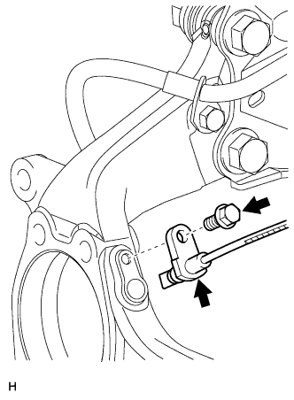
| 6. REMOVE FRONT SPEED SENSOR LH |
Disconnect the sensor connector.
Remove the sensor clip (labeled A), bolt (labeled B) and sensor clamp (labeled C).
Remove the sensor clip (labeled D), bolt (labeled E) and sensor clamp (labeled F).
Remove the bolt and sensor from the knuckle.
- NOTICE:
- Keep the sensor tip and sensor installation hole free from foreign matter.
| 7. REMOVE FRONT SPEED SENSOR RH |
- HINT:
- Use the same procedure for the RH side as for the LH side.
| 8. DISCONNECT FRONT STABILIZER LINK ASSEMBLY LH |
Remove the 2 nuts and stabilizer link.
| 9. DISCONNECT FRONT STABILIZER LINK ASSEMBLY RH |
- HINT:
- Use the same procedure for the RH side as for the LH side.
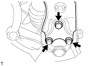
| 10. DISCONNECT FRONT SUSPENSION NO. 1 LOWER ARM SUB-ASSEMBLY LH |
Remove the bolt and 2 nuts.
Disconnect the lower arm from the ball joint.
| 11. DISCONNECT FRONT SUSPENSION NO. 1 LOWER ARM SUB-ASSEMBLY RH |
- HINT:
- Use the same procedure for the RH side as for the LH side.
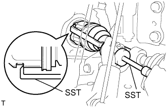
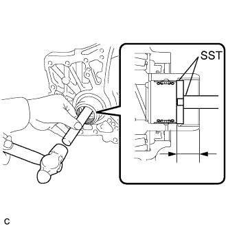
| 12. REMOVE FRONT DRIVE SHAFT ASSEMBLY LH |
Using SST, remove the front drive shaft.
- SST
- 09520-01010
09520-24010(09520-32040)
- NOTICE:
- Be careful not to damage the transaxle case oil seal, inboard joint boot and drive shaft dust cover.
- Be careful not to drop the drive shaft.
| 13. REMOVE FRONT DRIVE SHAFT ASSEMBLY RH |
- HINT:
- Use the same procedure for the RH side as for the LH side.
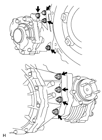
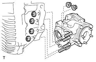
| 14. REMOVE TRANSFER ASSEMBLY |
except K111F:
Remove the 6 nuts, 2 bolts and transfer from the transaxle.
for K111F:
Remove the 6 nuts and transfer from the transaxle.
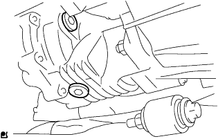
| 15. REMOVE TRANSAXLE CASE OIL SEAL LH |
Using SST, tap out the transaxle case oil seal.
- SST
- 09308-00010
| 16. REMOVE TRANSAXLE CASE OIL SEAL RH |
Remove the transaxle case oil seal RH (Outside).
Using a screwdriver with its tip wrapped with vinyl tape, pry out the oil seal.
- NOTICE:
- Be careful not to damage the housing.
Remove the transaxle case oil seal RH (Inside).
Using SST, tap out the oil seal.
- SST
- 09308-00010
- NOTICE:
- Be careful not to damage the differential case.
| 17. INSTALL TRANSAXLE CASE OIL SEAL LH |
Coat the lip of a new oil seal with MP grease.
Using SST and a hammer, tap in the oil seal.
- SST
- 09608-10010
09950-70010(09951-07200)
- Standard in depth:
- 3.0 to 4.0 mm (0.119 to 0.157 in.)
- NOTICE:
- Do not damage the lip of the oil seal.
| 18. INSTALL TRANSAXLE CASE OIL SEAL RH |
Install the transaxle case oil seal RH (Inside).
Coat the lip of the oil seal with MP grease.
Using SST and a hammer, tap in the oil seal.
- SST
- 09950-60010(09951-00410)
09950-70010(09951-07200)
- Standard depth:
- 21.5 to 22.5 mm (0.847 to 0.885 in.)
- NOTICE:
- Do not damage the lip of the oil seal.
Install the transaxle case oil seal RH (Outside).
Coat the lip of a new oil seal with MP grease.
Using SST and a hammer, tap in the oil seal.
- SST
- 09649-17010
09950-70010(09951-07200)
- Standard depth:
- 5.5 to 6.5 mm (0.217 to 0.255 in.)
- NOTICE:
- Do not damage the lip of the oil seal.
| 19. INSTALL TRANSFER ASSEMBLY |
except K111F:
Install the transfer to the transaxle with the 6 nuts and 2 bolts.
- Torque:
- 69 N*m{700 kgf*cm, 51 ft.*lbf}
for K111F:
Install the transfer to the transaxle with the 6 nuts and 2 bolts.
- Torque:
- 69 N*m{700 kgf*cm, 51 ft.*lbf}
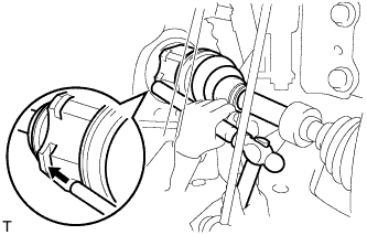
| 20. INSTALL FRONT DRIVE SHAFT ASSEMBLY LH |
Coat the splines of the inboard joint shaft with gear oil.
Align the shaft splines and tap in the drive shaft with a brass bar and hammer.
- NOTICE:
- Set the snap ring with the opening facing downwards.
- Be careful not to damage the oil seal, boot and dust cover.
| 21. INSTALL FRONT DRIVE SHAFT ASSEMBLY RH |
- HINT:
- Use the same procedure for the RH side as for the LH side.
| 22. CONNECT FRONT SUSPENSION NO. 1 LOWER ARM SUB-ASSEMBLY LH |
Connect the lower arm to the ball joint with the 2 bolts and nut.
- Torque:
- 92 N*m{938 kgf*cm, 68 ft.*lbf}
| 23. CONNECT FRONT SUSPENSION NO. 1 LOWER ARM SUB-ASSEMBLY RH |
- HINT:
- Use the same procedure for the RH side as for the LH side.
| 24. CONNECT FRONT STABILIZER LINK ASSEMBLY LH |
Install the link with the 2 nuts.
- Torque:
- 74 N*m{755 kgf*cm, 55 ft.*lbf}
| 25. INSTALL FRONT STABILIZER LINK ASSEMBLY RH |
- HINT:
- Use the same procedure for the RH side as for the LH side.
| 26. INSTALL FRONT SPEED SENSOR LH |
- NOTICE:
- To prevent interference with other parts, do not twist the painted line areas of the sensor wire when installing it.
Set the sensor into the knuckle, and then install the sensor with the bolt.
- Torque:
- 8.5 N*m{87 kgf*cm, 75 in.*lbf}
- NOTICE:
- Keep the sensor tip and sensor installation hole free from foreign matter.
- Firmly insert the sensor body into the knuckle before tightening the bolt.
- After installing the sensor to the knuckle, make sure that there is no clearance between the sensor stay and knuckle. Also make sure that no foreign matter is stuck between the parts.
- To prevent interference between the sensor and magnetic rotor, do not rotate the sensor body during or after the insertion of the sensor body to the knuckle.
Install the sensor clamp and sensor clip as follows.
Simultaneously perform the following: 1) hang the hook part of the sensor clamp (labeled A) on the part of the flexible hose bracket (labeled C); and 2) insert the hook part of the sensor clamp (labeled B) to the part of the flexible hose bracket (labeled D).
- NOTICE:
- Do not twist the sensor wire when installing the clamp.
Install the sensor clamp to the flexible hose clamp and flexible hose bracket with the bolt (labeled E).
- Torque:
- 18.5 N*m{189 kgf*cm, 14 ft.*lbf}
Insert the sensor clip (labeled F) into the hole on the absorber lower bracket.
Install the sensor clamp and sensor clip as follows.
Set the sensor clamp (labeled G) on the side member, and then install the bolt (labeled H).
- Torque:
- 8.5 N*m{87 kgf*cm, 75 in.*lbf}
- NOTICE:
- Do not twist the sensor wire when installing the clamp.
Insert the sensor clip (labeled I) into the hole on the apron.
Connect the sensor connector.
| 27. INSTALL FRONT SPEED SENSOR RH |
- HINT:
- Use the same procedure for the RH side as for the LH side.
| 28. INSTALL FRONT EXHAUST PIPE |
for 1AZ-FE:
Install front exhaust pipe (RAV4_ACA30 RM000001XBI002X_01_0002.html).
for 2AZ-FE:
Install front exhaust pipe (RAV4_ACA30 RM000001XBL01JX.html).
| 29. INSTALL NO. 1 ENGINE UNDER COVER |
- Torque:
- 103 N*m{1,050 kgf*cm, 76 ft.*lbf}
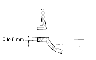
| 32. INSPECT MANUAL TRANSAXLE OIL |
Stop the vehicle in a level place.
Remove the transaxle filler plug and gasket.
Check that the oil level is between 0 to 5 mm (0 to 0.20 in.) from the bottom lip of the filler plug opening. If the result is not as specified, add transaxle oil.
- Oil grade:
- GL-4
- Viscosity:
- SAE 75W
- Standard capacity:
- 2.5 liters (2.6 US qts, 2.2 Imp. qts)
- NOTICE:
- Too much or too little oil will lead to transaxle problems.
- After adjusting the oil level, drive the vehicle and check the oil level again.
Check for oil leakage if the oil level is low.
Install the transaxle filler plug and a new gasket.
- Torque:
- 49 N*m{500 kgf*cm, 36 ft.*lbf}
Remove the transfer case plug No. 2 (for filler) and gasket.
Check that the oil level is between 0 to 5.0 mm (0 to 0.20 in.) from the bottom lip of the case plug (for filler) hole.
If the result is not as specified, add transfer oil.
- Oil grade:
- Hypoid gear oil SX API GL-5 or equivalent
- Viscosity:
- SAE 85W-90
- Standard capacity:
- 0.45 liter (0.48 US qts, 0.40 Imp. qts)
- NOTICE:
- When adding oil, pour it slowly.
- Too much or too little oil will lead to transfer problems.
When the oil level is too low, check for oil leakage.
Install a new gasket into the case plug (for filler) and then install the plug.
- Torque:
- 39 N*m{398 kgf*cm, 28 ft.*lbf}
| 35. INSPECT FRONT WHEEL ALIGNMENT |
Inspect wheel alignment (RAV4_ACA30 RM00000227W003X.html).