Lexus IS250 IS220d GSE20 ALE20 2AD-FHV LUBRICATION
ENGINE OIL COOLER - INSTALLATION
| 1. INSTALL ENGINE OIL PRESSURE SWITCH ASSEMBLY |
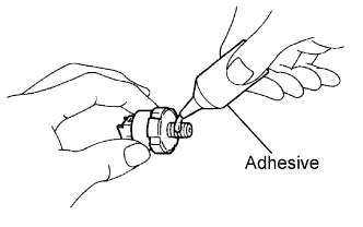
Apply adhesive to 2 or 3 threads of the oil pressure switch assembly.
- Adhesive:
- Toyota Genuine Adhesive 1344, Three Bond 1344 or equivalent
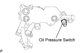
Install the oil pressure switch assembly to the No. 1 oil cooler bracket.
- Torque:
- 15 N*m{ 153 kgf*cm, 11 ft.*lbf}
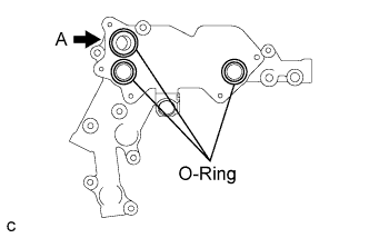
| 2. INSTALL NO. 1 OIL COOLER BRACKET |
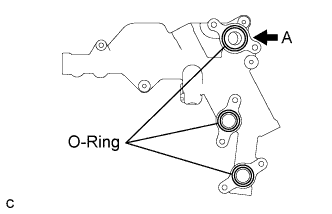
Apply engine oil to 2 new O-rings.
- NOTICE:
- Do not apply engine oil to the O-ring labeled A.
Install the 3 O-rings to the No. 1 oil cooler bracket.
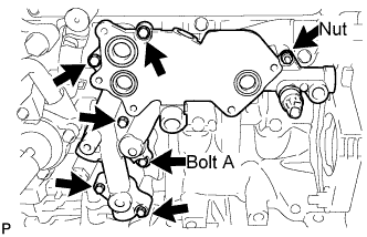
Install the No. 1 oil cooler bracket with the 6 bolts and nut.
- Torque:
- 11 N*m{ 112 kgf*cm, 8 ft.*lbf}
| Item | Length |
| Bolt A | 36 mm (1.42 in.) |
| Except A | 49 mm (1.93 in.) |
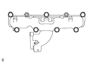
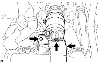
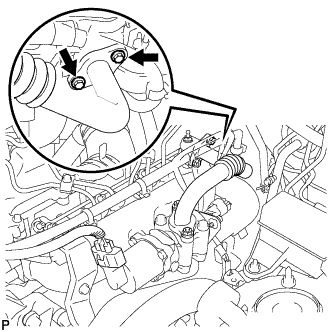
| 3. INSTALL NO. 1 TURBO OIL PIPE |
Install 2 new gaskets to the No. 1 turbo oil pipe.
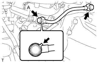
Install the No. 1 turbo oil pipe with the 2 union bolts.
- Torque:
- 35 N*m{ 357 kgf*cm, 26 ft.*lbf}
- NOTICE:
- Be sure to install union bolt A so that the gasket is positioned as shown in the illustration.
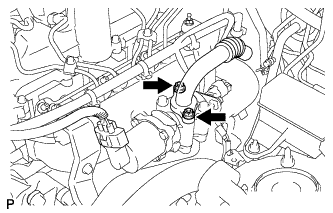
Install a new O-ring to the No. 3 water by-pass pipe.
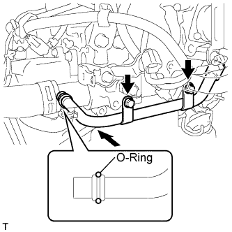
Connect the No. 3 water by-pass pipe with the 2 bolts.
- Torque:
- 21 N*m{ 214 kgf*cm, 16 ft.*lbf}
| 4. INSTALL OIL COOLER ASSEMBLY |
Apply engine oil to 2 new O-rings.
- NOTICE:
- Do not apply engine oil to the O-ring labeled A.
Install the 3 O-rings to the oil cooler bracket.
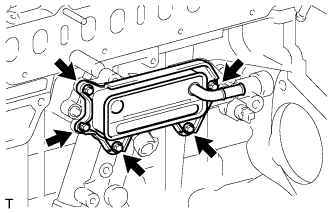
Install the oil cooler assembly with the 5 bolts.
- Torque:
- 11 N*m{ 112 kgf*cm, 8 ft.*lbf}
Install the No. 1 water by-pass hose with the clip.
Connect the connector to the oil pressure switch.
| 5. INSTALL INTAKE MANIFOLD SUB-ASSEMBLY |
Install a new intake manifold sub-assembly gasket to the cylinder head.
Install the intake manifold sub-assembly with the 7 bolts and 2 nuts.
- Torque:
- 23 N*m{ 235 kgf*cm, 17 ft.*lbf}
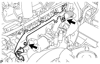
| 6. INSTALL INTAKE MANIFOLD STAY |
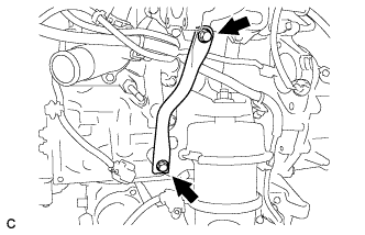
Install the intake manifold stay with the 2 bolts.
- Torque:
- 21 N*m{ 214 kgf*cm, 16 ft.*lbf}
| 7. INSTALL COMMON RAIL ASSEMBLY |
- NOTICE:
- In cases where the common rail is replaced, the fuel inlet pipe and injection pipe must also be replaced.
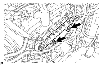
Temporarily install the common rail assembly with the 2 bolts.
Temporarily install the 2 fuel inlet pipes.
Temporarily install the No. 1, No. 2, No. 3 and No. 4 injection pipes.
Tighten the common rail assembly with the 2 bolts.
- Torque:
- 21 N*m{ 210 kgf*cm, 15 ft.*lbf}
Remove the No. 1, No. 2, No. 3 and No. 4 injection pipes.
Remove the 2 fuel inlet pipes.
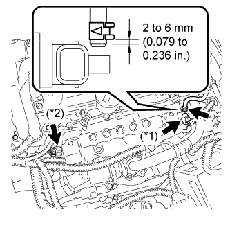
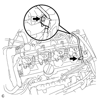
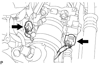
Connect the pressure discharge valve connector (*1).
Connect the fuel pressure sensor connector (*2).
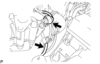
Using pliers, slide the clip to connect the fuel hose as shown in the illustration.
| 8. INSTALL INLET FUEL PIPE SUB-ASSEMBLY |
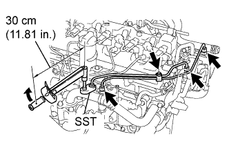
Temporarily install the 2 fuel inlet pipes, 2 injection pipe clamps and the bolt.
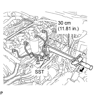
Using the SST, first tighten the nut at the common rail end of the fuel inlet pipe.
- SST
- 09023-38401
- Torque:
- 27 N*m{ 275 kgf*cm, 20 ft.*lbf}
- HINT:
If the pipe is deformed or twisted, or if it cannot be installed properly, replace the pipe with a new one.
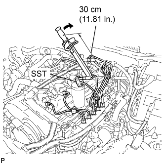
Using the SST, tighten the nut at the fuel supply pump of the fuel inlet pipe.
- SST
- 09023-38401
- Torque:
- 27 N*m{ 275 kgf*cm, 20 ft.*lbf}
- HINT:
If the pipe is deformed or twisted, or if it cannot be installed properly, replace the pipe with a new one.
Tighten the 2 injection pipe clamps with the bolt.
- Torque:
- 5.0 N*m{ 51 kgf*cm, 44 in.*lbf}
| 9. INSTALL NO. 4 INJECTION PIPE SUB-ASSEMBLY |
- NOTICE:
- In cases where an injector is replaced, the injection pipes must also be replaced.
Temporarily install the injection pipe.
Using the SST, first tighten the nut at the common rail end of the injection pipe.
- SST
- 09023-38401
- Torque:
- 27 N*m{ 275 kgf*cm, 20 ft.*lbf}
- HINT:
If the pipe is deformed or twisted, or if it cannot be installed properly, replace the pipe with a new one.
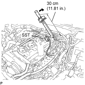
Using the SST, tighten the nut at the injector end of the injection pipe.
- SST
- 09023-38401
- Torque:
- 27 N*m{ 275 kgf*cm, 20 ft.*lbf}
- HINT:
If the pipe is deformed or twisted, or if it cannot be installed properly, replace the pipe with a new one.
| 10. INSTALL NO. 3 INJECTION PIPE SUB-ASSEMBLY |
- NOTICE:
- In cases where an injector is replaced, the injection pipes must also be replaced.
Temporarily install the 3 injection pipes and the 4 injection pipe clamps with the 2 bolts.
Using the SST, first tighten the nut at the common rail end of the injection pipe.
- SST
- 09023-38401
- Torque:
- 27 N*m{ 275 kgf*cm, 20 ft.*lbf}
- HINT:
If the pipe is deformed or twisted, or if it cannot be installed properly, replace the pipe with a new one.
Using the SST, tighten the nut at the injector end of the injection pipe.
- SST
- 09023-38401
- Torque:
- 27 N*m{ 275 kgf*cm, 20 ft.*lbf}
- HINT:
If the pipe is deformed or twisted, or if it cannot be installed properly, replace the pipe with a new one.
| 11. INSTALL NO. 2 INJECTION PIPE SUB-ASSEMBLY |
- HINT:
- Perform the same procedure as for the No. 3 injection pipe.
| 12. INSTALL NO. 1 INJECTION PIPE SUB-ASSEMBLY |
- HINT:
- Perform the same procedure as for the No. 3 injection pipe.
Tighten the 4 injection pipe clamps with the 2 bolts.
- Torque:
- 5.0 N*m{ 51 kgf*cm, 44 in.*lbf}
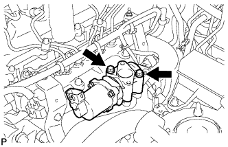
| 13. INSTALL NO. 1 FUEL PIPE |
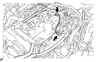
Install the No. 1 fuel pipe with the 2 bolts.
Connect the 2 fuel hoses and 2 clips.
| 14. REMOVE DIESEL THROTTLE BODY |
Install a new gasket and the diesel throttle body with the 2 nuts and 2 bolts.
- Torque:
- 21 N*m{ 214 kgf*cm, 16 ft.*lbf}
| 15. INSTALL NO. 4 AIR HOSE |
| 16. INSTALL AIR PIPE SUB-ASSEMBLY |
Connect the wire harness clamp.
Install the air pipe sub-assembly with the bolt.
- Torque:
- 5.0 N*m{ 51 kgf*cm, 44 in.*lbf}
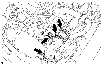
Connect the intake air temperature sensor connector.
Tighten the 3 hose bands.
- Torque:
- 4.0 N*m{ 41 kgf*cm, 35 in.*lbf}
Connect the 2 diesel throttle body connectors.
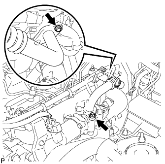
| 17. INSTALL NO. 1 WATER OUTLET PIPE |
Install the No. 1 water outlet pipe with the 3 bolts.
- Torque:
- 21 N*m{ 214 kgf*cm, 16 ft.*lbf}
Connect the 2 water hoses with the 2 bands.
Connect the manifold absolute pressure sensor connector and vacuum hose.
| 18. INSTALL EGR VALVE ASSEMBLY |
Install a new gasket and EGR valve assembly with the 2 bolts.
- Torque:
- 24 N*m{ 245 kgf*cm, 18 ft.*lbf}
| 19. INSTALL NO. 2 EGR PIPE SUB-ASSEMBLY |
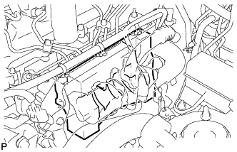
Install the intake manifold insulator.
- HINT:
- Insert the intake manifold insulator between the EGR valve and common rail to make contact with the intake manifold.
Install 2 new gaskets.
Temporarily install No. 2 EGR pipe with the bolt and nut.
Temporarily install the bolt and tighten the 2 bolts.
- Torque:
- 24 N*m{ 245 kgf*cm, 18 ft.*lbf}
Temporarily install the nut and tighten the 2 nuts.
- Torque:
- 24 N*m{ 245 kgf*cm, 18 ft.*lbf}
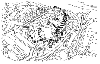
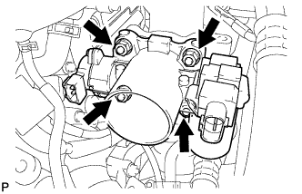
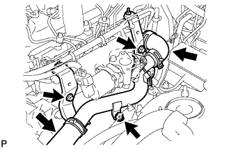
| 20. INSTALL WIRE HARNESS CLAMP BRACKET |
Install the wiring harness clamp bracket with the 2 bolts.
- Torque:
- 10 N*m{ 102 kgf*cm, 7 ft.*lbf}
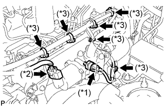
Connect the oil pressure switch assembly connector (*1).
Connect the EGR valve connector (*2).
Connect the 6 wire harness clamps (*3).
Connect the wire harness clamp.
| 21. CONNECT CABLE TO NEGATIVE BATTERY TERMINAL |
- Torque:
- 5.4 N*m{ 55 kgf*cm, 48 in.*lbf}
| 22. ADD ENGINE OIL |
Install the oil pan drain plug with a new gasket.
- Torque:
- 38 N*m{ 388 kgf*cm, 28 ft.*lbf}
Add engine oil according to the table below.
- Standard capacity:
Item Capacity Drain and refill with oil filter change 6.0 liters (6.3 US qts, 5.3 lmp. qts) Drain and refill without oil filter change 5.2 liters (5.5 US qts, 4.6 lmp. qts) Dry fill 6.7 liters (7.1 US qts, 5.9 lmp. qts)
| 23. ADD ENGINE COOLANT |
Tighten all the plugs.
- Torque:
- for cylinder block drain cock plug:
- 20 N*m{ 204 kgf*cm, 15 ft.*lbf}
Add engine coolant.
- Specified capacity:
- 8.9 liters (9.4 US qts, 7.8 lmp. qts)
- HINT:
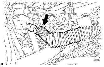
Slowly pour coolant into the radiator reservoir until it reaches the FULL line.
Squeeze the inlet and outlet radiator hoses several times by hand, and then check the level of the coolant.
If the coolant level is low, add coolant.
Install the radiator cap.
Bleed air from the cooling system.
- NOTICE:
- Before starting the engine, turn the A/C switch off.
Warm up the engine until the thermostat opens. While the thermostat is open, allow the coolant to circulate for several minutes.
- HINT:
- The thermostat open timing can be confirmed by squeezing the inlet radiator hose by hand, and sensing vibrations when the engine coolant starts to flow inside the hose.
- NOTICE:
- When squeezing the radiator hose:
Maintain the engine speed at 2,000 to 2,500 rpm.
Squeeze the inlet and outlet radiator hoses several times by hand to bleed air from the system.
- NOTICE:
- When squeezing the radiator hoses:
Stop the engine and wait until the engine coolant cools down to ambient temperature.
- CAUTION:
- Do not remove the radiator cap while the engine and radiator are still hot. Pressurized, hot engine coolant and steam may be released and cause serious burns.
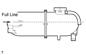
Check the coolant level in the reserve tank.
If the coolant level is low, add coolant to the reserve tank FULL line.
| 24. CHECK FOR ENGINE OIL LEAKS |
| 25. CHECK FOR ENGINE COOLANT LEAKAGE |
- CAUTION:
- Do not remove the radiator cap while the engine and radiator are still hot. Pressurized, hot engine coolant and steam may be released and cause serious burns.
- NOTICE:
- Before performing each inspection, turn the A/C switch off.
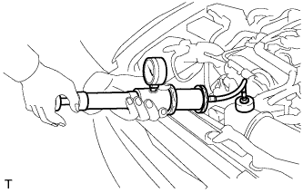
Fill the radiator with coolant and attach a radiator cap tester.
Warm up the engine.
Using a radiator cap tester, increase the pressure inside the radiator to 177 kPa (1.8 kgf/cm, 26 psi), and check that the pressure does not drop.
If the pressure drops, check the hoses, radiator and water pump for leaks. If no external leaks are found, check the heater core, cylinder block and cylinder head.
| 26. CHECK FOR FUEL LEAKAGE |
PERFORM ACTIVE TEST
Connect the intelligent tester to the DLC3.
Turn the engine switch ON (IG).
Turn the intelligent tester ON.
Enter the following menus: Powertrain / ENGINE / Active Test.
Perform the Active Test.
| Intelligent Tester Display | Test Details | Control Range | Diagnostic Notes |
| Test the Fuel Leak | Pressurize common rail internal fuel pressure, and check for fuel leaks | Stop/Start | Fuel pressure inside common rail pressurized to specified value and engine speed increased to 2,000 rpm when "Start" is selected Above conditions to be maintained while "Start" is selected |
| 27. CHECK ENGINE OIL LEVEL |
Warm up the engine, stop the engine and wait for 5 minutes. The oil level should be between the low and full level marks of the dipstick.
If the level is below the low level mark, check for leakage and add oil until it reaches the full level mark.
- NOTICE:
- Do not fill the engine oil above the full level mark.
| 28. INSTALL ENGINE ROOM SIDE COVER LH |
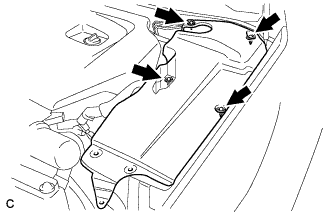
Install the side cover with the 4 clips.
| 29. INSTALL COOL AIR INTAKE DUCT SEAL |

Install the intake duct seal with the 11 clips.
| 30. INSTALL NO. 1 ENGINE COVER |
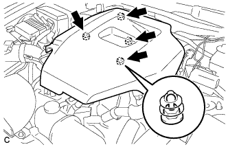
Install the No. 1 engine cover.
| 31. PERFORM INITIALIZATION |
Perform initialization .
- HINT:
- Certain systems need to be initialized after reconnecting the cable to the negative (-) battery terminal.